
A cushion block for fixing concrete flanging side formwork

A technology of concrete and pads, which is applied to the joints of formwork/formwork/work frame, the preparation of building components on site, construction, etc. It can solve problems such as difficulty in pouring, inability to place flat, time-consuming side forms, etc., to achieve The effect of ensuring accuracy

Active Publication Date: 2011-12-28
TIANSONG CONSTR GRP
View PDF5 Cites 0 Cited by
  • Summary
  • Abstract
  • Description
  • Claims
  • Application Information

AI Technical Summary

Problems solved by technology

It is required to complete the pouring of the flanging concrete before the initial setting of the floor slab, slab, and awning concrete to ensure the integrity of the two. However, this construction method often results in large deviations in the size and plane position of the concrete flanging. It is because after the floor concrete pouring is completed, the signs and marks for determining the plane position of the concrete flange are covered by the floor concrete, so that the plane position cannot be determined quickly and accurately, and the initial setting time of the concrete is short, and it takes a lot of time to fix the side formwork. Time, it is difficult to pour the flanging concrete before the initial setting of the floor slab or pick-up slab, and the awning concrete, etc., so the size and plane position of the concrete flanging deviate greatly

Method used


Image

  • A cushion block for fixing concrete flanging side formwork
  • A cushion block for fixing concrete flanging side formwork
  • A cushion block for fixing concrete flanging side formwork

Examples


Embodiment Construction

[0025] The present invention will be further described below with specific embodiment, see Figure 1-10 :

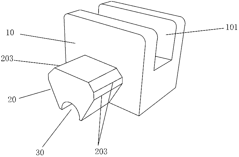
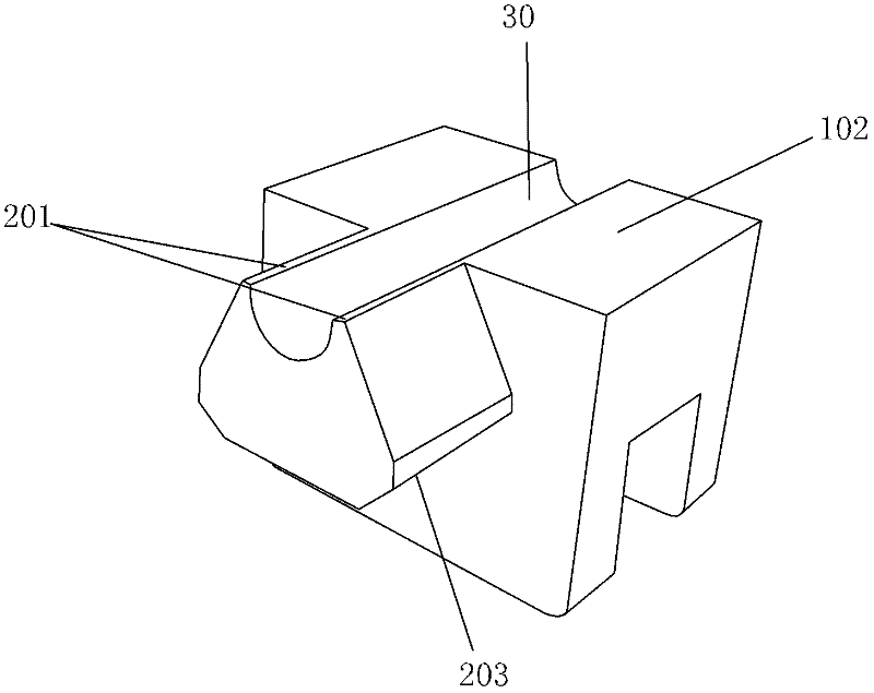
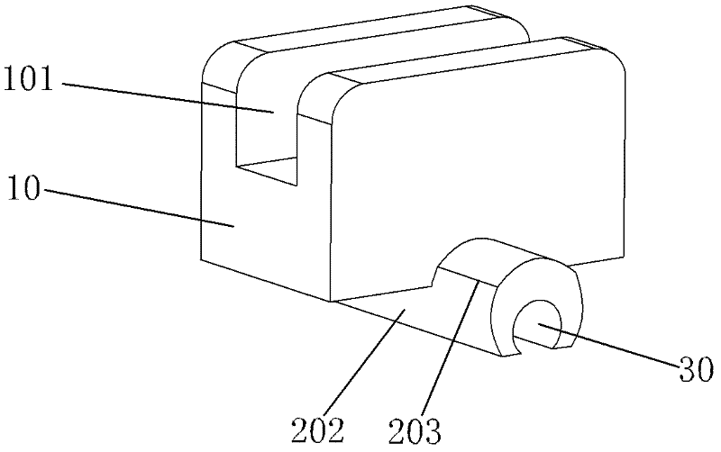
[0026] A spacer for fixing concrete flanging side forms, in the center of the spacer body 10 from the upper plane to the bottom plane, there is a groove 101 for positioning formwork longitudinally through, and in the spacer body 10 parallel to the groove 101 There is an installation position 20 extending outwards from the center of the lower part of one side, the bottom plane 201 of the installation position 20 is flush with the bottom plane 102 of the pad body 10 or the bottom 202 of the installation position 20 is exposed outside the bottom plane 102 of the pad body 10, At the center of the bottom 202 of the installation position 20 and the bottom of the block body 10 is a through steel bar installation groove 30 perpendicular to the groove 101 .

[0027] The cross-section of the installation position 20 mentioned above is a regular trapezoid or an inverted trapezoid,...


PUM


Abstract

The invention belongs to the technical field of buildings and particularly relates to a cushion block for fixing a concrete flanged side mold. In the cushion block provided by the invention, a longitudinal through groove for a positioning template is formed in the center in the direction from an upper plane to a bottom plane of a cushion block body; an installation part is formed by externally extending the lower part of one side of the cushion block body, in parallel to the groove, in a centered manner; the bottom plane of the installation part is in parallel to that of the cushion block body or is exposed out of that of the cushion block body; and a through reinforcing steel bar installation groove which is perpendicular to the groove is formed at the bottom of the installation part and at the bottom of the cushion block body in a centered manner. According to the cushion block provided by the invention, the movements (comprising up-to-down and left-to-right movements) of the bottom feet of the side mold can be better limited in the pouring course of concrete under the condition that the concrete flanged side mold is firstly erected, thereby ensuring the accuracy of the concrete flanging dimension and the plane position. The cushion block provided by the invention does not lead to the generation of a percolating water channel which passes through a component and is fixed on surface layer plate ribs of concrete components such as a floor slab or a cantilever slab, a rain tent and the like, and does not pass through the integral component and the concrete components such as the floor slab or the cantilever slab, the rain tent and the like.

Description

Technical field: [0001] The invention belongs to the technical field of construction, and particularly refers to a cushion block for fixing the side form of the concrete flange, which ensures that no seepage channel occurs and the correctness of the shape and size of the flange itself is ensured when the concrete flange and the concrete component are integrally poured into concrete . Background technique: [0002] Concrete flanging around kitchens, bathrooms, and floors with waterproof requirements, as well as concrete flanging at the root of pick-up boards and awnings protruding from the outer wall, is one of the keys to preventing water leakage. The function of concrete flanging is to block external or internal water leakage. Water leaks to the inside or outside. In order to avoid construction joints between the concrete flanging and the floor slab or the canopy due to the separate pouring of the concrete, thereby forming a nearly through-through leakage water channel, it...

Claims


Application Information

Patent Timeline
IPC IPC(8): E04G17/00
Inventor 颜传国孙海峰刘传卿徐锦锋林伟蔡国熙
Owner TIANSONG CONSTR GRP
Learn More