Microgrid reactive power compensation method and system

A power compensation and micro-grid technology, applied in the direction of reactive power adjustment/elimination/compensation, reactive power compensation, etc., can solve the problems of inability to measure the distribution of reactive power in micro-grids, mixed power sources and loads, and no technical solutions. Achieve the effects of avoiding additional power loss and local overheating, solving negative sequence current, and improving utilization

Active Publication Date: 2011-12-28
北京四方华能电气设备有限公司
View PDF4 Cites 20 Cited by
  • Summary
  • Abstract
  • Description
  • Claims
  • Application Information

AI Technical Summary

Problems solved by technology

When the microgrid operates in grid-connected mode, it can usually be determined by measuring the current and voltage at the PCC switch (that is, at the common connection point where the microgrid is connected to the external large grid) according to the existing reactive power compensation technology Reactive power compensation requirements of the entire microgrid. However, when the microgrid operates in the isolated grid mode, since its power supply and load are mixed together, no power condition of any node can reflect the reactive power of the entire microgrid. In terms of balance, it is impossible to measure the reactive power distribution of the microgrid with the existing reactive power compensation technology, so the adjustment of the reactive power of the microgrid cannot use the existing methods and equipment, and there is no relevant technical solution that can be applied to the microgrid Reactive Power Compensation

Method used


Image

  • Microgrid reactive power compensation method and system
  • Microgrid reactive power compensation method and system
  • Microgrid reactive power compensation method and system

Examples


Embodiment Construction

[0030] In order to better explain the present invention and for a better understanding, the present invention will be described in more detail below through specific embodiments in conjunction with the accompanying drawings.

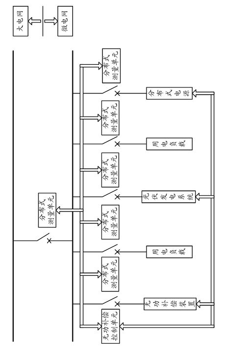
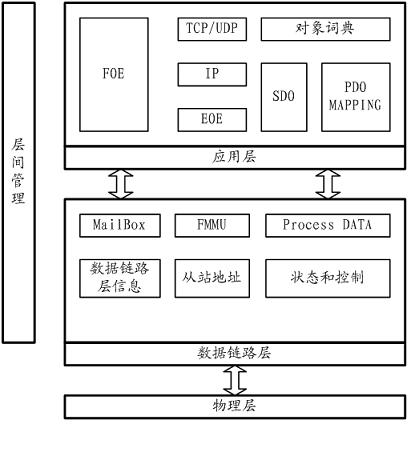
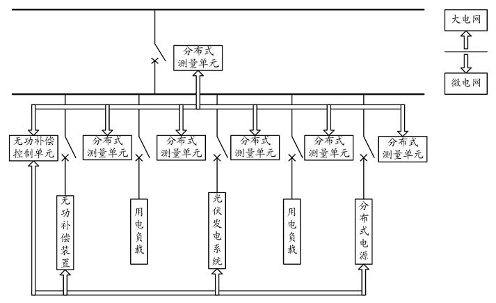
[0031] See figure 1 with figure 2 , The present invention provides a microgrid reactive power compensation system, which is mainly used for reactive power compensation when the microgrid is operating in an isolated grid. It includes a distributed measurement unit, a reactive power compensation control unit, a reactive power compensation device, and a communication unit. . The microgrid includes a distributed power supply with reactive power regulation output.

[0032] The distributed measurement unit is mainly used to measure the distribution of active and reactive power of different branches of the microgrid, and send the collected data to the reactive power compensation control unit.

[0033] Preferably, the distributed measurement unit has a clock synchro...


PUM


Abstract

The invention relates to a reactive power compensation method and a reactive power compensation system for a micro power grid. The system comprises a distributed measuring unit, a reactive power compensation control unit, a reactive power compensation unit and a communication unit. The micro power grid comprises a distributed power supply with reactive regulation output. For the micro power grid operated in an isolated network mode, the overall reactive power balance condition of the micro power grid is obtained by measuring the active and reactive power distribution conditions of each branchcircuit of the micro power grid, and a reactive power compensation device or the reactive power compensation device and the distributed power supply are subjected to reactive regulation in the micro power grid according to a specific isolated network reactive control strategy to realize the reactive power compensation of the micro power grid. The power factor of the micro power grid can be measured and corresponding reactive power compensation is performed according to the power factor when the micro power grid is operated in a grid-connected mode and in the isolated network mode.

Description

Technical field [0001] The invention relates to a reactive power compensation method and system for a power system, in particular to a method and system for reactive power compensation of a microgrid. Background technique [0002] Reactive power compensation technology plays an extremely important role in reducing energy loss in existing power systems. However, the application of existing reactive power compensation technologies is usually limited to conventional power systems. , Distribution, and use phase separation system, so it has a clear node can be used to measure the power factor of the entire conventional power system, usually by measuring the current and voltage data at the node to calculate the corresponding power factor, and can further Determine the corresponding reactive power compensation strategy. For example, the voltage and current measured on the incoming switch of the user's substation can reflect the actual demand for reactive power compensation of the entir...

Claims


Application Information

Patent Timeline
Patent Type & Authority Applications(China)
IPC IPC(8): H02J3/18
CPCY02E40/30
Inventor 杜宏
Owner 北京四方华能电气设备有限公司
Why Eureka
Try Eureka