Cutting insert, cutting tool, and cutting method of workpiece using the cutting tool

一种切削镶刀、切削工具的技术,应用在刀夹的附件、铣削切削刀片、制造工具等方向,能够解决耐缺损性差等问题,达到减少切削阻力、优异耐缺损性、低切削阻力的效果

Inactive Publication Date: 2011-12-28
KYOCERA CORP
View PDF6 Cites 6 Cited by
  • Summary
  • Abstract
  • Description
  • Claims
  • Application Information

AI Technical Summary

Problems solved by technology

[0003] However, as the main edge portion 46 is inclined, the thickness of the cutting insert 20 (the distance between the first end surface 28 and the second end surface 30 ) decreases, so the problem of poor chipping resistance occurs.

Method used


Image

  • Cutting insert, cutting tool, and cutting method of workpiece using the cutting tool
  • Cutting insert, cutting tool, and cutting method of workpiece using the cutting tool
  • Cutting insert, cutting tool, and cutting method of workpiece using the cutting tool

Examples


Embodiment Construction

[0024]

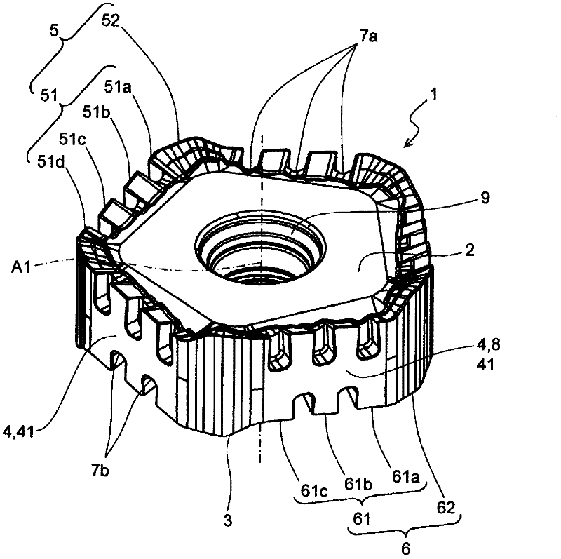
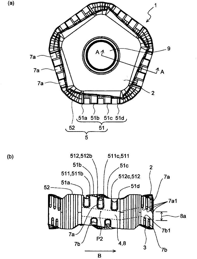
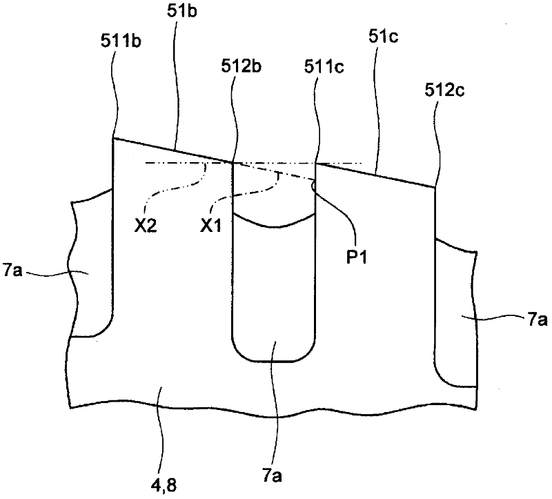
[0025] Below, refer to Figure 1 to Figure 5 , an embodiment of the cutting insert according to the present invention will be described in detail. The cutting insert 1 of the present embodiment is as figure 1 and figure 2 As shown, it generally has an upper surface 2, a lower surface 3, a side surface 4 connected to the upper surface 2 and the lower surface 3, a through hole 9 (installation hole) penetrating from the upper surface 2 to the lower surface 3, and the upper surface 2 and the side surface. The upper cutting edge 5 at the intersection of 4 and the lower cutting edge 6 at the intersection of the lower surface 3 and the side 4. In addition, the side surface 4 has at least one upper concave portion 7a that extends to the upper surface 2 in the thickness direction and divides the upper cutting edge 5 into a plurality of divided upper cutting edges 51a to 51d, and extends to the lower surface 3 in the thickness direction and divides the lower cutting edge ...


PUM


Abstract

Provided is a cutting insert comprising side surfaces located between the upper surface and the lower surface thereof and having upper recesses extending to the upper surface, and also comprising separated upper cutting edges located along the line of intersection between the upper surface and each side surface and separated from each other by upper recesses. Each of the separated upper cutting edges has a first end and a second end and is tilted so as to approach the lower surface from the first end toward the second end. The separated upper cutting edges comprise first separated upper cutting edges and second separated upper cutting edges, and each first separated upper cutting edge and each second separated upper cutting edge are adjacent to each other. In a side view, the first end of the second separated upper cutting edge is located at a position above the intersection between a line extended from the first separated upper cutting edge and a line passing through the first end of the second separated upper cutting edge and parallel to the center axis of the cutting insert, and the position is the same as or below the position of the second end of the first separated upper cutting edge. Also provided are a cutting tool provided with the cutting insert and a method of cutting a material to be cut using the cutting tool.

Description

technical field [0001] The present invention relates to a cutting insert, a cutting tool, and a method for cutting a workpiece using the cutting tool. Background technique [0002] In the past, regarding cutting inserts (hereinafter sometimes referred to as inserts.), in JP2008-544872 Figure 4 et al. disclose a cutting insert 20 in which the main edge portion 46 is inclined. It is preferable to incline the main edge portion 46 in this way from the viewpoint of reducing cutting resistance. [0003] However, as the main edge portion 46 is inclined, the thickness of the cutting insert 20 (the distance between the first end surface 28 and the second end surface 30 ) decreases, which causes a problem of poor chipping resistance. [0004] Therefore, cutting inserts with low cutting resistance and excellent chipping resistance are required. [0005] Patent Document 1: Japanese PCT Publication No. 2008-544872. Contents of the invention [0006] One of the objects of the presen...

Claims


Application Information

Patent Timeline
Patent Type & Authority Applications(China)
IPC IPC(8): B23B27/14B23B27/00B23C5/06B23C5/20
CPCB23C2200/128B23C2200/205B23C2200/0444B23C5/202B23C5/06B23C2200/326B23C2200/203Y10T407/1962Y10T407/192Y10T409/303808Y10T407/1936Y10T407/23Y10T407/2274Y10T407/2272
Inventor 古贺健一郎
Owner KYOCERA CORP
Why Eureka
Try Eureka