table cutting machine

A desktop cutting machine, cutting machine technology, applied in the direction of metal sawing equipment, sawing machine, metal processing equipment, etc., can solve the problems of reducing the operating efficiency of the desktop cutting machine, sliding rod obstruction, discomfort, etc., to improve operating efficiency, Effect of ensuring uniformity and reducing rear installation space

Active Publication Date: 2011-12-28
MAKITA CORP
View PDF13 Cites 10 Cited by
  • Summary
  • Abstract
  • Description
  • Claims
  • Application Information

AI Technical Summary

Problems solved by technology

[0008] However, when using the desktop cutting machine disclosed in the above-mentioned Patent Document 3, because the slide bar protrudes from the upper part of the supporting arm part to the front and is always in a fixed state in the state protruding above the material to be cut, it is difficult to perform cutting work. , the slide bar becomes an obstacle when aligning the ink line with the tip of the knife, so that the operator has to make an uncomfortable posture to see the tip of the knife, which reduces the working efficiency of the desktop cutting machine.
Especially for large-scale cutting materials, when only one set of sliding mechanisms is used to ensure a longer sliding distance of the cutting machine body, the sliding rod becomes longer, so the distance that the sliding rod protrudes to the front becomes longer, This will further reduce the operating efficiency of the table cutting machine

Method used


Image

  • table cutting machine
  • table cutting machine
  • table cutting machine

Examples


Embodiment Construction

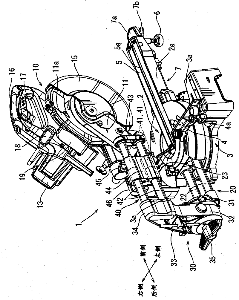
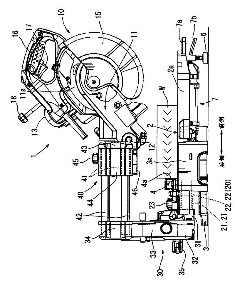
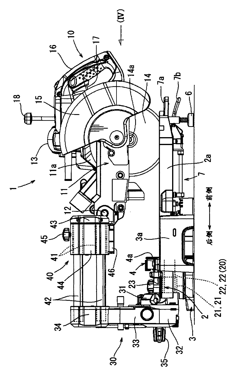
[0026] The following is based on Figure 1 to Figure 8 Embodiments of the present invention will be described. figure 1 It is a figure which shows the whole table cutting machine 1 in this embodiment. figure 1 The above-mentioned desktop cutting machine 1 shown has: a workbench 2, which is circular and used to place the material W to be cut; a base 3, on which the workbench 2 is supported and rotatable; a cutting machine body 10, which is located on Above workbench 2. And it can be flipped up and down.

[0027] Two fixed table parts 3 a are provided on both left and right sides of the table 2 . The two fixed table parts 3 a are provided on the left and right sides of the base 3 and are integrally formed with the base 3 . The table 2 is supported on the upper surface of the base 3 between the two fixed table parts 3 a. Between the two fixed table parts 3a, the positioning fence 4 for positioning the to-be-cut material is straddled and installed. The positioning baffle 4 i...


PUM


Abstract

In a table cutting machine capable of sliding a main body of the cutting machine in the backward and forward direction for the purpose of processing a large size material to be cut, a rearward installation space can be reduced by configuring the cutting machine in such a way that a slide bar of a slide mechanism for slidably supporting the main body of the cutting machine is fixed while a bearing side is adapted to be movable. However, this has caused a problem that the fixed slide bar obstructs an operation. In accordance with the present invention, the rearward installation space can be reduced and good visibility of the edge of a blade can be obtained, and thus an operational performance is improved. Slide mechanisms (20 and 40) arranged in two stages in the vertical direction are used for obtaining a long slide distance for a main body of a cutting machine (10). For the upper stage slide mechanism, there is adopted the slide mechanism (40) of a pattern 2 in which a slide bar (42) is fixed. This allows the rearward installation space of the slide mechanism (40) to be reduced, and ensures good visibility of the edge of a blade.

Description

technical field [0001] The invention relates to a desktop cutting machine, the body of the cutting machine can not only move up and down to the direction of the cut material fixed on the workbench, but also slide along the direction of the workbench surface. Background technique [0002] Disclosed in the following patent document 1 is a technology related to a desktop cutting machine, which uses a motor as a driving power source and has a cutting machine body with a rotatable circular cutting knife. It can not only move up and down, but also slide along the direction of the workbench. When using this desktop cutting machine, the cutting machine body can be operated downwards so that the rotating cutting knife cuts into the material to be cut. The wider cut material is cut and processed. [0003] In addition, Patent Document 2 discloses a desktop cutting machine. Because it has two sets of upper and lower sliding mechanisms, the cutting machine body can slide a farther dist...

Claims


Application Information

Patent Timeline
Patent Type & Authority Applications(China)
IPC IPC(8): B23D47/02B23D45/04
CPCB23D45/048B23D47/02Y10T83/7693
Inventor 青山修司
Owner MAKITA CORP
Why Eureka
Try Eureka