Valve element, valve, selector valve, and trap device

A technology for switching valves and spools, which is applied to valve devices, valve heating/cooling devices, transportation and packaging, etc. It can solve problems such as time required for maintenance, difficulty in confirming reliable sealing of sealing parts, and difficulty in finding fault locations. Achieve the effect of small setting space, simple structure, and easy to find faults

Inactive Publication Date: 2008-01-16
TOKYO ELECTRON LTD
View PDF1 Cites 9 Cited by
  • Summary
  • Abstract
  • Description
  • Claims
  • Application Information

AI Technical Summary

Problems solved by technology

In this way, the switching mechanism of Patent Document 1 is a switching mechanism with good sealing performance or sealing responsiveness, but there is a problem that it is difficult to confirm whether the sealing part is reliably sealed.
In addition, in the case of the above-mentioned conversion mechanism, there is a problem that it is difficult to find the location of the fault or it takes time to repair, so it needs to be improved.

Method used


Image

  • Valve element, valve, selector valve, and trap device
  • Valve element, valve, selector valve, and trap device
  • Valve element, valve, selector valve, and trap device

Examples


Embodiment Construction

[0050] Hereinafter, preferred embodiments of the present invention will be described with reference to the drawings.

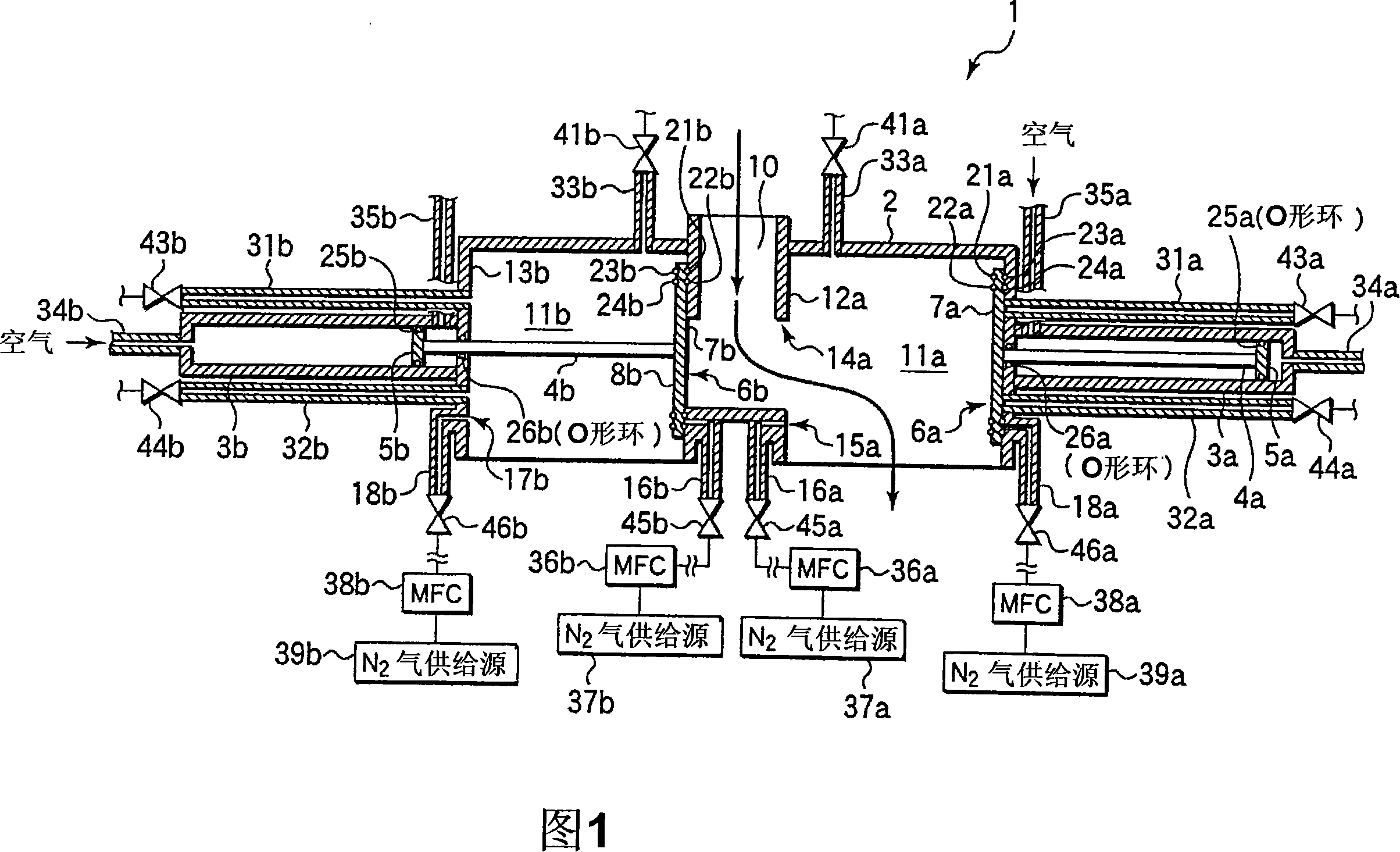
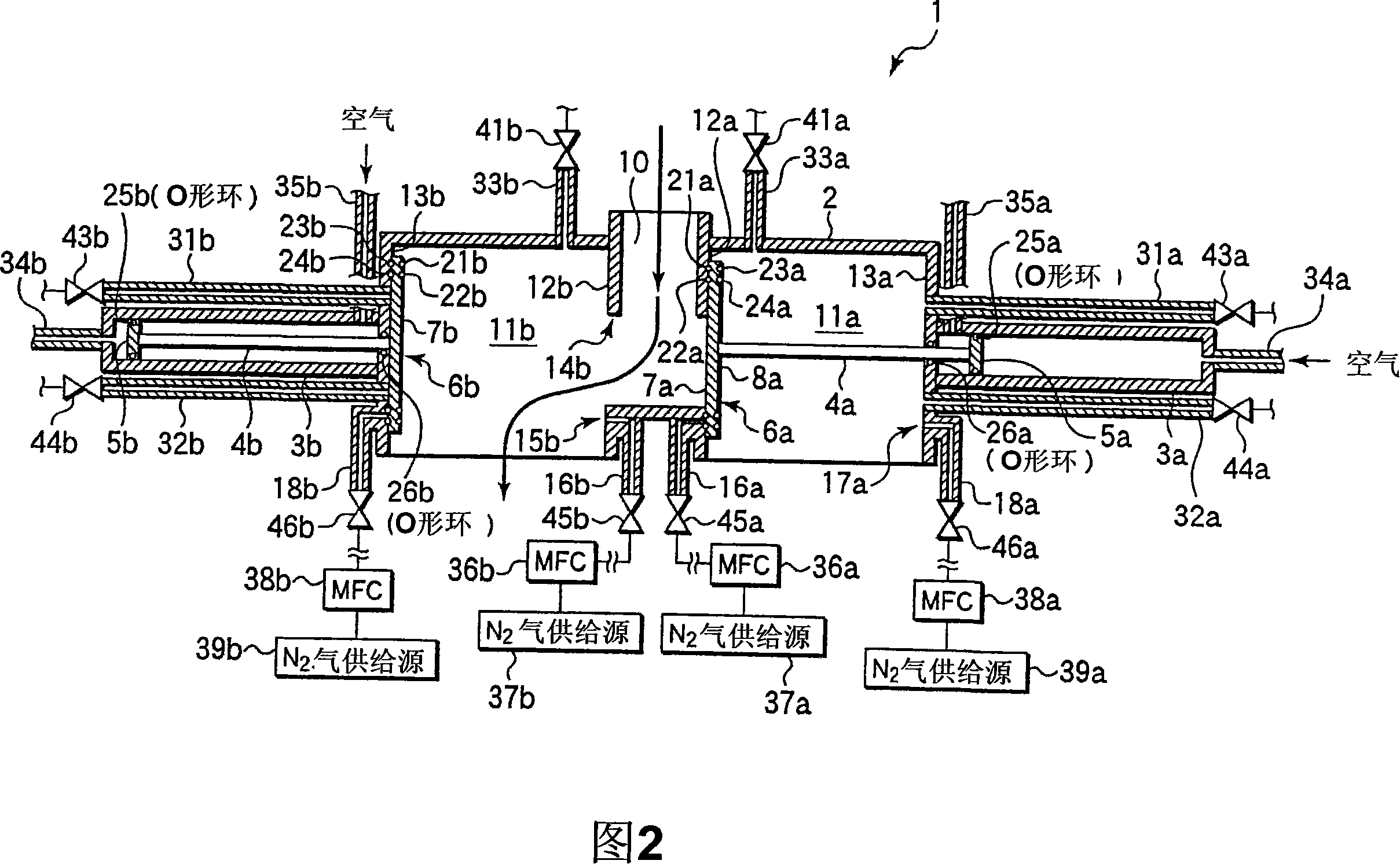
[0051] 1 and 2 are cross-sectional views showing a schematic configuration of a valve mechanism according to an embodiment of the present invention. The valve 1 can be used as a switching means etc. which alternately switches the flow path of the exhaust gas which flows into the trap which catches the substance in the exhaust gas from a vacuum processing chamber. The valve 1 is provided with an inflow portion 10 for allowing fluid to flow into the housing 2 , and has a substantially symmetrical structure around the inflow portion 10 . That is, in the casing 2, the first flow path 11a and the second flow path 11b are formed at intervals of the above-mentioned inflow portion 10 . A seal plate 6a serving as a valve body driven by the air cylinder 3a is provided in the first flow path 11a. A seal plate 6b serving as a valve element driven by the air cylinder 3b ...


PUM


Abstract

A valve element, a valve, a selector valve, and a trap device. When a fluid flows in the first flow passage (11a) of the valve (1), an operating plate (5a) is slidably moved by leading air from an air lead-in passage (35a) into an air cylinder (3a) to drive a shaft (4a) so as to move a sealing plate (6a) backward until the second sealing surface (8a) of the sealing plate (6a) is brought into contact with a wall (13a). An air cylinder (3b) is advanced to such a position that the first sealing surface (7b) of a sealing plate (6b) is brought into contact with a wall (12b) to seal an opening (14b).

Description

technical field [0001] The present invention relates to a spool, a valve, a switching valve and a collecting device, and in particular, to a spool, a valve, a switching valve and a collecting device having the switching valve which are suitable for use on a discharge path of exhaust gas from a vacuum device. Background technique [0002] When manufacturing devices such as electronic parts, various processes such as film formation and etching are performed on substrates such as semiconductor wafers and glass substrates in processing chambers such as vacuum chambers. During such processing, an exhaust path is connected to the processing chamber, and exhaust is performed through the exhaust path. In the exhaust gas, unreacted processing gas and reaction products are mixed, and harmful substances or reusable substances are also included. Therefore, collection means are provided to catch them without releasing them into the atmosphere. [0003] As the collection device, the fol...

Claims


Application Information

Patent Timeline
Patent Type & Authority Applications(China)
IPC IPC(8): F16K11/044B01D8/00B01J3/00B01J3/02F16K1/36F16K37/00F16K49/00H01L21/205H01L21/3065
CPCF16K51/02F16K49/002F16K11/207H01L21/67017F16K11/044Y10T137/87917
Inventor 津田荣之辅
Owner TOKYO ELECTRON LTD
Why Eureka
Try Eureka