High-efficiency and accurate grooving boring bar and grooving method

A boring bar and grooving technology, applied in the direction of boring bars, etc., can solve problems such as inconvenient operation, low efficiency, and unsafety, and achieve the effects of easy operation, high precision, and simple structure

Active Publication Date: 2013-08-28
KUNMING WATER PUMP FACTORY
View PDF8 Cites 0 Cited by
  • Summary
  • Abstract
  • Description
  • Claims
  • Application Information

AI Technical Summary

Problems solved by technology

With this kind of traditional boring tool, since the boring tool has no feed device in the radial direction, it is necessary to hit one end of the boring tool with a hammer to realize the feeding and grooving when cutting grooves, which is inconvenient, unsafe and less efficient.

Method used


Image

  • High-efficiency and accurate grooving boring bar and grooving method
  • High-efficiency and accurate grooving boring bar and grooving method
  • High-efficiency and accurate grooving boring bar and grooving method

Examples


Embodiment Construction

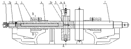
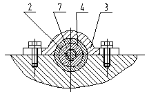
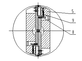
[0018] As shown in the figure, an efficient and accurate grooving boring bar includes a boring bar 7 connected to the power head at one end, a boring sleeve 4 set outside the boring bar, a boring disc 5 installed in the middle of the boring bar, and a boring disc installed The cutting knife 6 inside the boring bar is provided with a push rod coaxial with the boring bar and facing the cutting knife 6 in the middle of the boring bar. The bottom end of the cutting knife extends to the inside of the boring bar until it contacts the top cone , the top 2a of the ejector rod against the cutter is conical, and the outer end of the ejector rod 2 is located at the outer end of the boring bar. Such as image 3 As shown, a horizontal reset lever 8 is provided on the side of the cutter body of the cutter, and a longitudinal through hole leading to the reset lever is provided at the top of the boring cutter disc 5, and a reset spring 9 that promotes the reset of the cutter is installed in t...


PUM


Abstract

The invention relates to a high-efficiency and accurate grooving boring bar and a grooving method. The method comprises the following steps of: placing the boring bar (7) sleeved with the boring sleeve (4) in a workpiece to be grooved and pressing by using a positioning press plate; moving the boring cutter (5) head to a position to be grooved; aligning the cutter (6) with a groove to be cut; starting the boring bar; rotating the hand wheel (1) in a direction opposite to the rotation direction of the boring bar (7) to drive the push rod (2) to forwards move; and jacking up the cutter by using the conical top part (2a) for cutting the groove. The machining method is simple, convenient and high-efficiency, and grooving precision is high.

Description

technical field [0001] The invention relates to the technical field of processing tools and methods for cutting grooves in holes. Background technique [0002] In the machining process, it is more common to use ordinary lathes to cut grooves in holes, and it is relatively easy to cut grooves in order from large to small hole diameters. However, if the aperture is small to large, it is very difficult to cut grooves, especially the S-type pump in the water pump, whose pump body is relatively large, and it is not easy to process on a lathe. The traditional method is to use the boring bar with boring tool to process, that is, to open a square hole at the appropriate position of the boring bar, install the boring tool in the square hole, lock it with the hexagon socket head screw, turn the boring bar, and drive the boring tool to process the groove . With this traditional boring tool, since the boring tool has no tool feed device in the radial direction, it is necessary to hit...

Claims


Application Information

Patent Timeline
Patent Type & Authority Patents(China)
IPC IPC(8): B23B29/02
Inventor 刘绍荣李吉荣袁渝昆
Owner KUNMING WATER PUMP FACTORY
Why Eureka
Try Eureka