Hydraulic system of excavator

A hydraulic system and excavator technology, applied in the field of excavator and excavator hydraulic system, can solve the problems of hydraulic system heating, energy waste, low pressure, etc., and achieve the effects of reducing heat generation, reducing cost, and low energy consumption

Active Publication Date: 2015-07-15
ZHEJIANG STRONGER HYDRAULIC
View PDF6 Cites 0 Cited by
  • Summary
  • Abstract
  • Description
  • Claims
  • Application Information

AI Technical Summary

Problems solved by technology

As the control oil circuit of the hydraulic system of the excavator, the pilot oil circuit requires low pressure and small flow rate, which causes most of the oil provided by the pilot pump 1 to overflow through the safety valve, which not only causes energy waste but also causes Hydraulic system heating and various problems caused by heating

Method used


Image

  • Hydraulic system of excavator
  • Hydraulic system of excavator

Examples


Embodiment 1

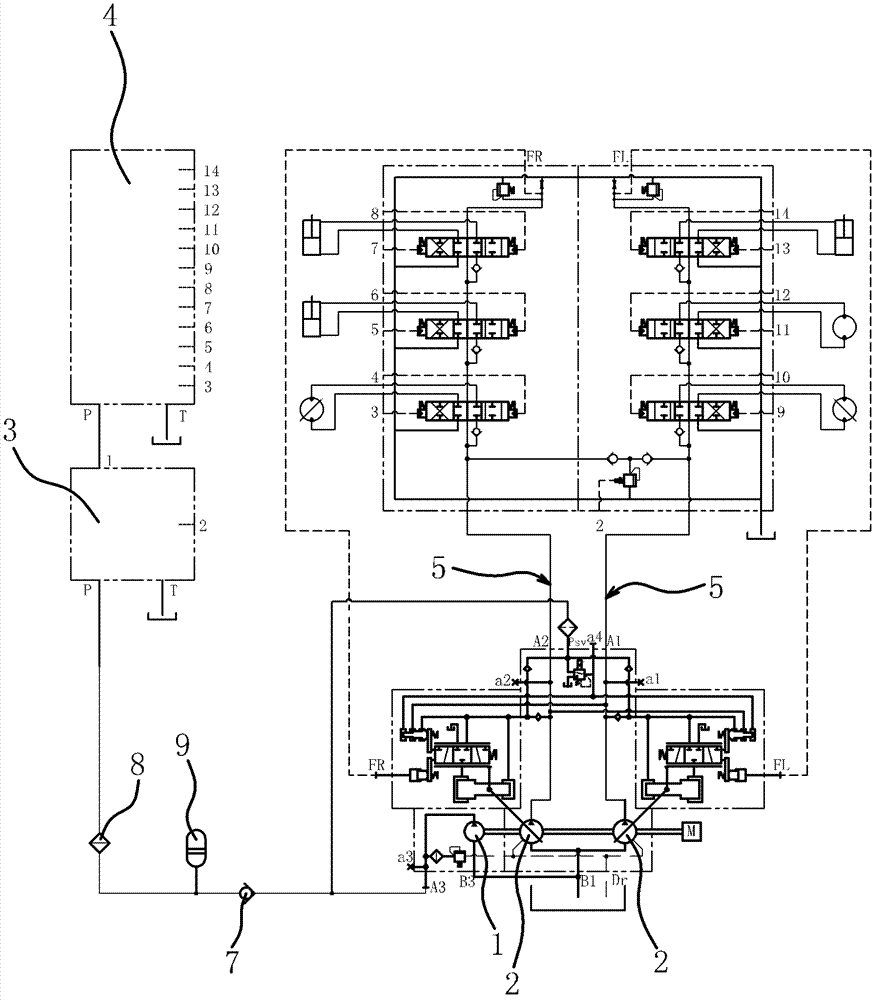
[0027] like figure 2 As shown, the hydraulic system of the excavator includes the main oil circuit subsystem and the pilot oil circuit subsystem. The main oil circuit subsystem includes two main pumps 2 and a main oil circuit 5 communicating with the main pumps 2 one by one. The pilot oil circuit subsystem includes a pilot valve assembly 4 and a solenoid valve assembly 3 communicating with the pilot valve assembly 4 .

[0028] The oil inlet of the solenoid valve assembly 3 communicates with the two main oil circuits 5 through the oil supply pipeline 6 and the shuttle valve 10; that is, the two inlets of the shuttle valve 10 communicate with the two main oil circuits 5 respectively , The oil supply pipeline 6 communicates with the outlet of the shuttle valve 10 .

[0029] More specifically, the communication pipeline 11 between the two inlets of the shuttle valve 10 and the corresponding main oil passage 5 is provided with a throttle valve capable of reducing the influence o...

Embodiment 2

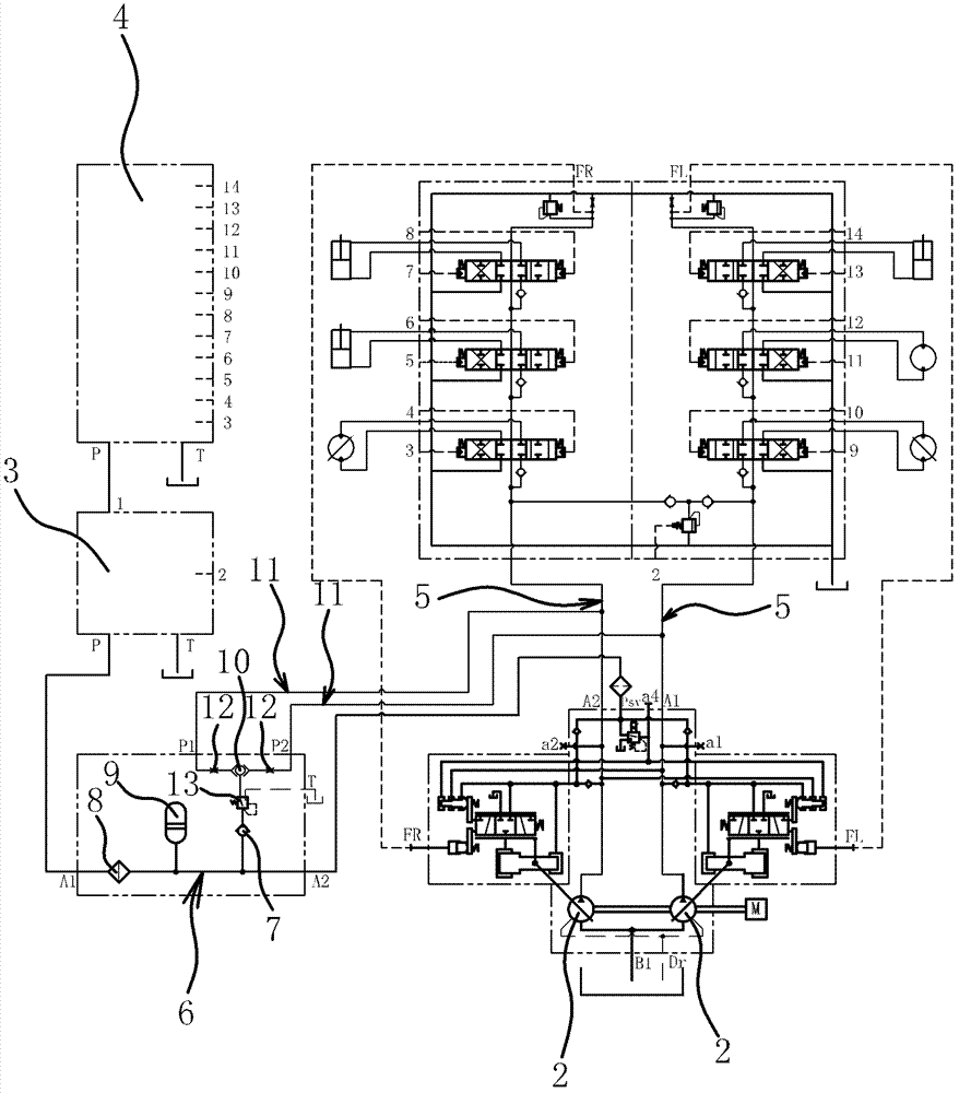
[0034] The structure and principle of this embodiment are basically the same as that of Embodiment 1, the difference is that: the connecting pipeline 11 between the two inlets of the shuttle valve 10 and the corresponding main oil circuit 5 is provided with a one-way throttle valve, The one-way throttle valve can not only reduce the influence of the pressure fluctuation of the main oil circuit 5 on the pressure of the oil supply pipeline 6 , but also prevent the hydraulic oil from flowing back to the main oil circuit 5 . A relief pressure reducing valve 13 and a filter 8 are sequentially provided on the oil supply pipeline 6 from the outlet of the shuttle valve 10 to the oil inlet of the solenoid valve assembly 3 .

Embodiment 3

[0036] The structure and principle of this embodiment are basically the same as those of the first embodiment, except that the oil inlet of the solenoid valve assembly 3 communicates with any one of the main oil circuits 5 through the oil supply pipeline 6 . A throttle valve 12, a relief pressure reducing valve 13, a one-way valve 7 and a filter 8 are sequentially arranged on the oil supply line 6 from the main oil line 5 to the solenoid valve assembly 3, and the relief of the relief pressure relief valve 13 The orifice communicates with the fuel tank.


PUM


Abstract

The invention provides a hydraulic system of an excavator, belonging to the technical field of engineering machinery and solving the technical problems of high energy consumption, low use stability and the like of the traditional hydraulic system of the excavator. The hydraulic system of the excavator comprises a main oil way subsystem and a pilot oil way subsystem, wherein the main oil way subsystem comprises a main pump and a main oil way communicated with the main pump; the pilot oil way subsystem comprises a pilot valve assembly and an electromagnetic valve assembly communicated with the pilot valve assembly; and an oil inlet of the electromagnetic valve assembly is communicated with the main oil way through an oil supply pipeline. The invention has the advantages of low cost, high stability, low energy consumption, energy saving and emission reduction and the like.

Description

technical field [0001] The invention belongs to the technical field of engineering machinery, and relates to an excavator, in particular to an excavator hydraulic system. Background technique [0002] An excavator is an earth-moving machine that uses a bucket to excavate materials above or below the bearing surface, and loads them into transport vehicles or unloads them to the stockyard. The excavated materials are mainly soil, coal, silt, and pre-loosened soil and rock. Judging from the development of construction machinery in recent years, the development of excavators is relatively fast, and excavators are one of the most important construction machinery in engineering construction. [0003] As the power system of the excavator, the hydraulic system plays a vital role in the overall performance of the excavator. like figure 1 As shown, at present, the hydraulic system of the excavator is composed of the engine, the main pump 2, the pilot pump 1, the control valve and t...

Claims


Application Information

Patent Timeline
Patent Type & Authority Patents(China)
IPC IPC(8): E02F9/22
Inventor 蔡志方尹铁军刘汉斌李春光杨实高月平邹卫
Owner ZHEJIANG STRONGER HYDRAULIC
Why Eureka
Try Eureka