Flatness detecting device and method
A detection device and flatness technology, which is applied in the field of measuring instruments, can solve the problems of few points, slow speed, large error, etc., and achieve the effect of meeting production requirements and fast data speed
- Summary
- Abstract
- Description
- Claims
- Application Information
AI Technical Summary
Problems solved by technology
Method used
Image
Examples
Embodiment 1
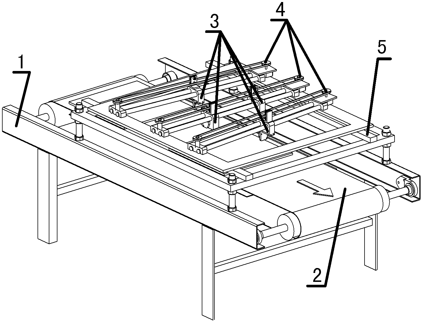
[0027] Embodiment 1: refer to Figure 1~9 . The flatness detection device includes a detection frame 1, the upper end of the detection frame 1 is provided with a conveying device 2 for longitudinally moving the object 9 to be tested, and a plurality of probes 3 are arranged above the conveying device 2 and are respectively connected with the probes 3 and can make each probe 3 Consists of a transmission mechanism 4 for lateral reciprocating movement.
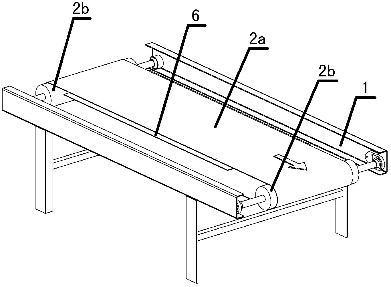
[0028] The conveying device 2 includes two guide rollers 2b and a conveyor belt 2a sleeved between the two guide rollers 2b, the two guide rollers 2b are respectively located at the upper part of the front end and the upper part of the rear end of the detection frame 1, and the two guide rollers 2b The ends are movably connected with the detection frame 1 respectively, and one of the guide rollers 2b is a driving guide roller driven by a motor. A glass backing plate 6 connected to the detection frame 1 is arranged between the t...
Embodiment 2
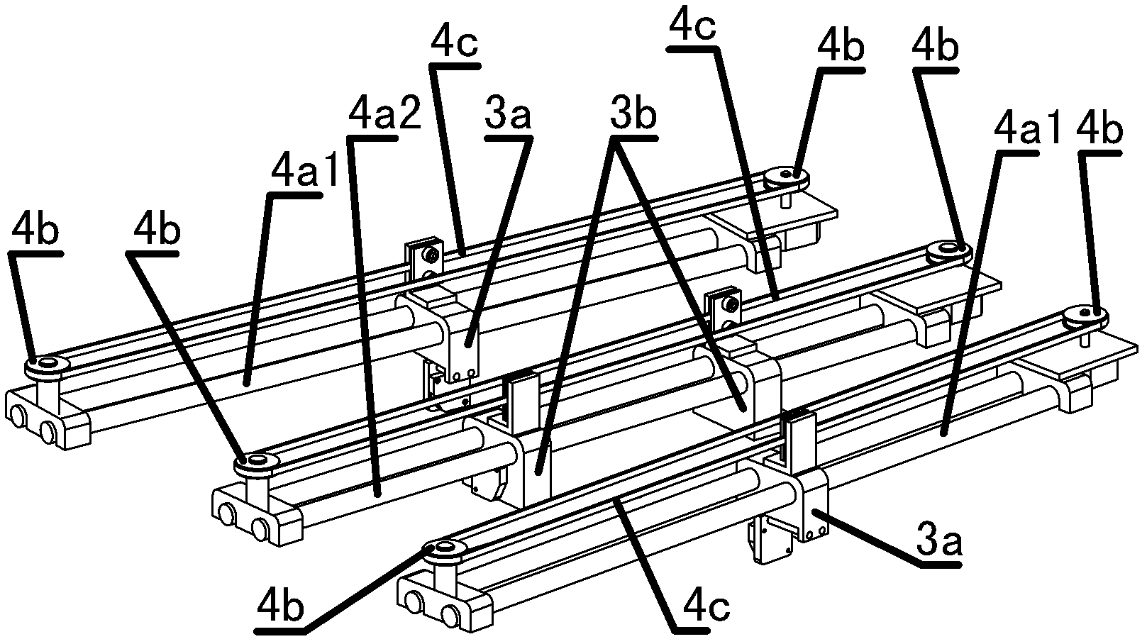
[0031] Embodiment 2: refer to Figure 6 and 7 . On the basis of Embodiment 1, the transmission mechanism 4 is composed of two sets of first guide rails 4a1 arranged front and back and a second guide rail 4a1 arranged between the two sets of first guide rails 4a2, and the middle parts of the two sets of first guide rails 4a1 are respectively placed There are a first probe 3a1 and a second probe 3a2, a third probe 3b1 and a fourth probe 3b2 are arranged in the middle of the second guide rail 4a2, and the third probe 3b1 and the fourth probe 3b2 are respectively connected with the timing belt above the second guide rail 4a2 The front and rear sides of 4c are connected.
Embodiment 3
[0032] Embodiment 3: refer to Figure 1~9 . A method for flatness detection with a flatness detection device, the transmission mechanism 4 of the flatness detection device is based on Embodiment 2, and its detection method includes the following steps:
[0033] a) Place the tested item 9 on the conveyer belt 2a, and send it in at a constant speed by the conveyer belt 2a;
[0034] b) Four probes 3 are arranged above the conveyor belt, assuming that the object under test 9 is provided with a rectangular frame 9a along the boundary, the first probe 3a1 and the second probe 3a2 can slide back and forth laterally along the first guide rail 4a1 respectively, and While the object under test 9 is fed at a constant speed, the detection scans of the two diagonals 9a4 of the rectangular frame 9a and the detection scans of the front side 9a2 and the rear side 9a1 of the rectangular frame 9a are respectively completed in sequence; the third probe 3b1 and the fourth probe 3b1 The probe 3b...
PUM
 Abstract
Description
Claims
Application Information
 - R&D
- Intellectual Property
- Life Sciences
- Materials
- Tech Scout
- Unparalleled Data Quality
- Higher Quality Content
- 60% Fewer Hallucinations
Browse by: Latest US Patents, China's latest patents, Technical Efficacy Thesaurus, Application Domain, Technology Topic, Popular Technical Reports.
© 2025 PatSnap. All rights reserved.Legal|Privacy policy|Modern Slavery Act Transparency Statement|Sitemap|About US| Contact US: help@patsnap.com


