High-speed camera shooting and PIV synchronous measurement system suitable for moving boundary flow field

A technology of synchronous measurement and high-speed camera, which is used in measurement devices, testing of machine/structural components, fluid dynamics tests, etc. It can solve problems such as inability to synchronously measure, and achieve the effect of improving measurement efficiency and processing accuracy.

Active Publication Date:
View PDF6 Cites 12 Cited by
  • Summary
  • Abstract
  • Description
  • Claims
  • Application Information

AI Technical Summary

Problems solved by technology

[0004] In order to solve the problem in the prior art that the high-speed imaging and PIV (laser particle image velocimetry) of the flow field around the moving boundary cannot be measured synchronously, a high-speed imaging and PIV synchronous measurement system suitable for the moving boundary flow field disclosed in the present invention needs to The technical problem to be solved is to realize the simultaneous measurement of the high-speed camera of the flow field around the moving boundary and the laser particle image velocity measurement, thereby improving the experimental measurement efficiency of the flow field around the moving boundary, and the accuracy of the experimental data processing can be improved through the synchronous measurement

Method used


Image

  • High-speed camera shooting and PIV synchronous measurement system suitable for moving boundary flow field
  • High-speed camera shooting and PIV synchronous measurement system suitable for moving boundary flow field
  • High-speed camera shooting and PIV synchronous measurement system suitable for moving boundary flow field

Examples


Embodiment 1

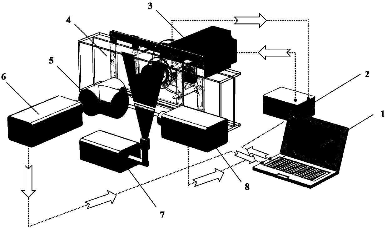
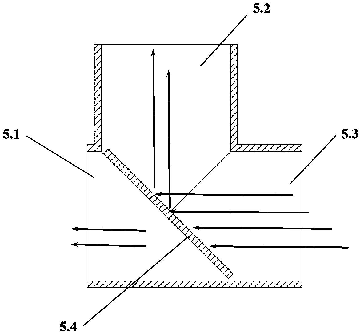
[0022] Such as figure 1 , figure 2 , image 3 As shown, the system includes a computer 1 , a drive controller 2 , a drive device 3 , a water tunnel test section 4 , a synchronous measurement device 5 , a PIV camera 6 , a laser generator 7 , and a high-speed camera 8 . The driving device 3 is installed on the rear side of the water tunnel test section 4, and the tested hydrofoil is arranged between the driving device 3 and the water tunnel test section 4; the driving device 3 is connected to the computer 1 through the driving controller 2. A PIV camera 6 is arranged on the other side of the water tunnel test section 4, a laser generator 7 is arranged directly under the hydrofoil of the water tunnel test section 4, a synchronous measurement device 5 is arranged between the PIV camera 6 and the water tunnel test section 4, and the synchronous measurement device 5 is equipped with PIV shooting port 5.1, high-speed camera shooting port 5.2, and synchronous shooting port 5.3; PIV...


PUM


Abstract

The invention discloses a high-speed camera shooting and PIV synchronous measurement system suitable for a moving boundary flow field, and belongs to the technical field of fluid mechanics experiments. The high-speed camera shooting and PIV synchronous measurement system suitable for the moving boundary flow field comprises a computer, a driving controller, a driving device, a water tunnel test section, a synchronous measuring device, a PIV camera, a laser generator and a high-speed camera. Through the perspective effect of a one-way transparent mirror, laser particle image velocimetry is carried out on a measured water wing flow field by the PIV camera, and through the reflection effect of the one-way transparent mirror, full flow field shooting is carried out on the measured water wing flow field by the high-speed camera so as to realize high-speed camera shooting and PIV synchronous measurement. By keeping a lens and a PIV shooting port of the PIV camera on a same shaft system and keeping a lens and a high-speed camera shooting port of the high-speed camera on a same shaft system, the accuracy of the synchronous measurement is ensured. The high-speed camera shooting and PIV synchronous measurement system suitable for the moving boundary flow field can realize the synchronous measurement of the moving boundary flowing-around flow field high-speed camera shooting and the laserparticle image velocimetry, the measurement efficiency is further improved, and the experimental data processing precision can be improved through the synchronous measurement.

Description

technical field [0001] The invention relates to a high-speed camera and PIV synchronous measurement system suitable for a dynamic boundary flow field, belonging to the technical field of fluid mechanics experiments. Background technique [0002] In the field of aerospace, in order to avoid dynamic stall, structural flutter and resonance, the dynamic characteristics of oscillating airfoils have been paid more and more attention. In the study of hydraulic machinery, the additional force generated by the rotation and the disturbance of the static and dynamic components have an important impact on the turbulent flow process, the development of the boundary layer, and the temporal and spatial distribution of the flow structure. It is the focus and difficulty of the research. In the transient process of propeller, turbo pump, hydraulic turbine start-up and shutdown, runaway, load increase and decrease, etc., the transient flow in the transient process will change the effective an...

Claims


Application Information

Patent Timeline
Patent Type & Authority Applications(China)
IPC IPC(8): G01M10/00
CPCG01M10/00
Inventor 王国玉张孟杰黄彪张敏弟吴钦
Why Eureka
Try Eureka