Velocity field and density field synchronous measurement system and method

A technology of synchronous measurement and density field, applied in velocity/acceleration/impact measurement, fluid velocity measurement, full-field flow measurement, etc., can solve the problems that cannot reflect the influence of temperature distribution in the heat transfer process, limit the application of NPLS technology, and achieve synchronization Accurate measurement results, improved acquisition frequency and accuracy

Pending Publication Date: 2020-07-28
NORTHEAST DIANLI UNIVERSITY
View PDF14 Cites 12 Cited by
  • Summary
  • Abstract
  • Description
  • Claims
  • Application Information

AI Technical Summary

Problems solved by technology

However, in the process of coupling flow and heat transfer such as natural convection heat transfer and supercritical flow heat transfer, the distribution of nano-tracer particles used in NPLS technology is not affected by the temperature distribution, and cannot reflect the heat transfer process or temperature. The influence of the distribution on the density distribution limits the application of NPLS technology in the field of flow heat transfer, so it is urgent to develop a simultaneous measurement technology of velocity field and density field suitable for incompressible fluid flow heat transfer process

Method used


Image

  • Velocity field and density field synchronous measurement system and method
  • Velocity field and density field synchronous measurement system and method
  • Velocity field and density field synchronous measurement system and method

Examples


specific Embodiment approach 1

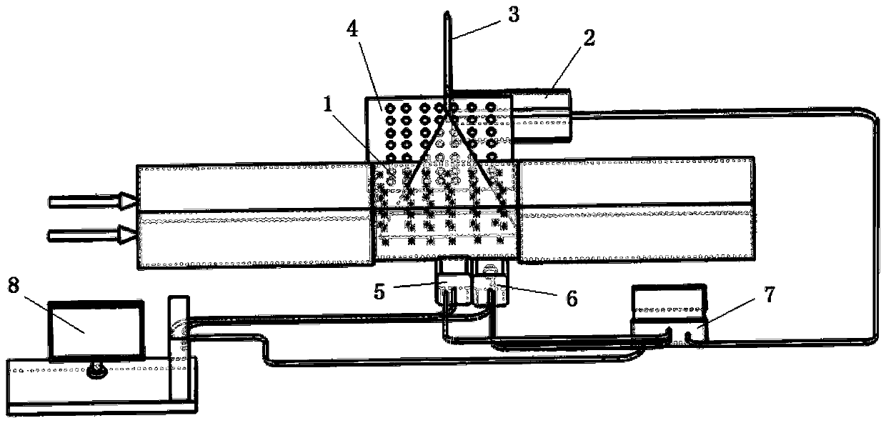
[0067] The laser 2 in this embodiment is a Nd:YAG dual-cavity laser with a pulse frequency of 15 Hz, a laser wavelength of 550 nm, a pulse energy of 120 MJ, and a pulse width of 10-12 ns. The laser light source emitted by the laser 2 is adjusted to be a sheet light source, the thickness of the sheet light is 1mm, and the flow field is irradiated vertically.

[0068] The first CCD camera 5 and the second CCD camera 6 are both high-speed frame-crossing CCD cameras. The shortest frame-crossing time of the two high-speed frame-crossing CCD cameras is 0.5μs, and the acquisition frequency can reach 1280×800pixels when the camera resolution is guaranteed 1630Hz. BOS camera (the second CCD camera 6) is equipped with a narrow-band filter with a wavelength of 550nm±5nm in front of the lens to only capture the laser signal, while the lens of the PIV camera (the first CCD camera 5) is equipped with a single-pass filter with a wavelength of 580nm Only fluorescent signals are captured. Th...

specific Embodiment approach 2

[0073] This embodiment provides a supercritical CO 2 Simultaneous measurement system of velocity field and density field in flow heat transfer process.

[0074] Supercritical CO 2 Flow through a rectangular stainless steel pipe with a size of 10mm*10mm*600mm, apply a certain amount of heat on the outer wall, and connect a visual test section with a pipe length of 100mm at the outlet, and the mass flow rate of the working fluid is 600kg / (m 2 ·s), the temperature range is 35-50°C, and the pressure is 8MPa. The specific settings are as follows:

[0075] 1. Determine the position of the test section, camera, background image, and laser lighting; take the location of the test section as a reference, adjust the laser beam to pass through the center of the test section vertically; place the PIV and BOS cameras side by side, facing the experimental measurement section , the background image is facing the BOS camera with the test section as the center, and the two cameras and the ba...


PUM

PropertyMeasurementUnit
sizeaaaaaaaaaa

Abstract

The invention relates to a velocity field and density field synchronous measurement system and method. The system comprises a visual test pipeline, a laser emission system, a background image target plate, a first CCD camera and a second CCD camera. The method comprises the following steps that fluorescent tracer particles are added into a fluid to be measured, a laser device irradiates laser to the fluid to be measured, and the first CCD camera shoots images of the fluorescent tracer particles at different moments to obtain distribution of a velocity field; and the second CCD camera synchronously shoots a to-be-measured fluid image with the background image target plate as the background when laser irradiates the to-be-measured fluid to obtain distribution of the density field. Synchronous measurement of the velocity field and the density field is achieved.

Description

technical field [0001] The invention relates to the field of fluid physical field parameter measurement, in particular to a velocity field and density field synchronous measurement system and method. Background technique [0002] The velocity field is an important parameter to study the heat transfer characteristics of fluid flow, and the method of measuring the velocity field is mainly Particle Image Velocimetry (PIV for short). For natural convection heat transfer, supersonic flow and supercritical flow heat transfer processes, the fluid density changes drastically, and the compressibility cannot be ignored. Obtaining the distribution characteristics of the velocity field and density field at the same time is the key to obtaining the law of flow heat transfer, revealing the mechanism of flow heat transfer, An important basis for developing accurate turbulent transport models. [0003] Yi Shihe and others from National University of Defense Technology invented Nanoparticle...

Claims


Application Information

Patent Timeline
Patent Type & Authority Applications(China)
IPC IPC(8): G01P5/20G01P5/00G01N9/24
CPCG01P5/20G01P5/001G01N9/24
Inventor 牛晓娟于博文洪文鹏刘忠彦
Owner NORTHEAST DIANLI UNIVERSITY
Why Eureka
Try Eureka