
Thermal imaging temperature measurement and fault location inspection system

A fault location and image technology, applied in radiation pyrometry, measuring devices, optical radiation measurement, etc., can solve problems such as the inability to accurately locate faults, and achieve the effect of improving accuracy and temperature measurement accuracy

Inactive Publication Date: 2012-01-04
CHINA AGRI UNIV
View PDF7 Cites 25 Cited by
  • Summary
  • Abstract
  • Description
  • Claims
  • Application Information

AI Technical Summary

Problems solved by technology

[0005] The technical problem to be solved by the present invention is: how to provide a thermal imaging temperature measurement and fault location patrol system to overcome the defect that the traditional solution cannot realize the precise location of the fault location

Method used


Image

  • Thermal imaging temperature measurement and fault location inspection system
  • Thermal imaging temperature measurement and fault location inspection system
  • Thermal imaging temperature measurement and fault location inspection system

Examples


Embodiment Construction

[0039] The specific implementation manners of the present invention will be further described in detail below in conjunction with the accompanying drawings and embodiments. The following examples are used to illustrate the present invention, but are not intended to limit the scope of the present invention.

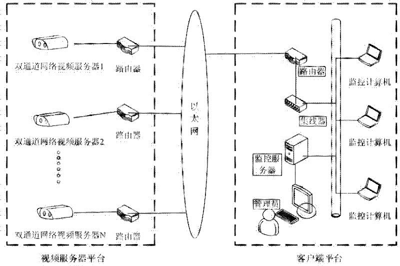
[0040] figure 1 It is a structural diagram of the thermal imaging temperature measurement and fault location inspection system described in the embodiment of the present invention. Such as figure 1 As shown, the thermal imaging temperature measurement and fault location inspection system includes: a video server platform and a client platform connected through Ethernet.

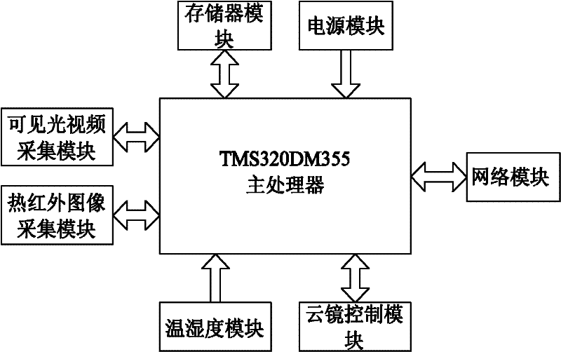
[0041] The video server platform mainly includes multiple groups of interconnected dual-channel network video servers and routers, and the dual-channel network video server includes a thermal infrared camera and a visible light camera for collecting and preprocessing visible light images and thermal inf...


PUM


Abstract

The invention discloses a thermal imaging temperature measurement and fault location inspection system and relates to the field of automatic detection. The inspection system comprises a video server platform and a client platform which are connected with each other, wherein the video server platform is used for acquiring and preprocessing an invisible light image and a thermal infrared image of an inspection field and sending the preprocessed invisible light image and thermal infrared image to the client platform; and the client platform is used for processing the received invisible light image and the thermal infrared image by using an image registration algorithm and a thermal imaging temperature measurement algorithm and displaying the processed invisible light image and thermal infrared image, and sending a control command to the video server platform. By the image registration and thermal imaging temperature measurement method, the precision of fault location and temperature measurement is improved.

Description

technical field [0001] The invention relates to the technical field of automatic detection, in particular to a thermal imaging temperature measurement and fault location inspection system. Background technique [0002] The thermal imaging temperature measurement and fault location patrol system is to use computer vision, communication, image processing, embedded and other technologies to collect the thermal state information of the monitored objects and visible light video images and other parameters using embedded technology and transmit them to the user monitoring terminal through the network. , by processing the feedback information to the embedded system, so as to achieve functions such as temperature measurement, fault location and automatic inspection. It is an intelligent system that can obtain the thermal state information of the monitored objects in real time and detect the location of the fault point in time. It is an effective means that can be widely used in vari...

Claims


Application Information

Patent Timeline
IPC IPC(8): G01J5/00
Inventor 王库何智波李寒贾稼边昊一
Owner CHINA AGRI UNIV
Learn More