Device for synchronously blanking scraps and removing burrs for progressive die

A mold synchronization and deburring technology, which is applied in the direction of metal processing equipment, forming tools, manufacturing tools, etc., can solve the problems of difficulty in removing burrs at the edge joints, no guarantee of safety, and increased manufacturing costs, so as to save punching machines and manpower Resources, improve poor quality, improve the effect of economic benefits

Inactive Publication Date: 2012-01-11
SHENZHEN EVA PRECISION TECH GRP CO LTD
View PDF7 Cites 16 Cited by
  • Summary
  • Abstract
  • Description
  • Claims
  • Application Information

AI Technical Summary

Problems solved by technology

However, in the stamping process of the metal mold, sharp burrs often appear on the truncated surface after punching, which makes it inevitable that the operator will come into contact with the sharp burrs when the hardware parts are assembled into a product, which is very easy to cause damage to the operation Personnel injury, safety accidents, in addition, some hardware parts are to be assembled in electronic appliances, the burrs on the hardware parts may fall on the electronic components, greatly increasing the possibility of circuit failure, so now product designers It is required that the hardware parts should not have burrs
Although the existing metal continuous mold can easily remove the burr, but it is very difficult to remove the burr at the edge joint of the connected product, because the edge is always connected to the workpiece until the final process before punching, and generally cannot be done in this mold after punching. Deburring in the next process usually requires additional processing to remove the burrs, or additional stamping to remove the burrs, which increases the manufacturing cost
Moreover, the process of adding stamping to remove burrs is a single stamping, which must be manually operated to pick and place the workpiece, which is inefficient and has no guarantee of safety.

Method used


Image

  • Device for synchronously blanking scraps and removing burrs for progressive die
  • Device for synchronously blanking scraps and removing burrs for progressive die
  • Device for synchronously blanking scraps and removing burrs for progressive die

Examples


Embodiment Construction

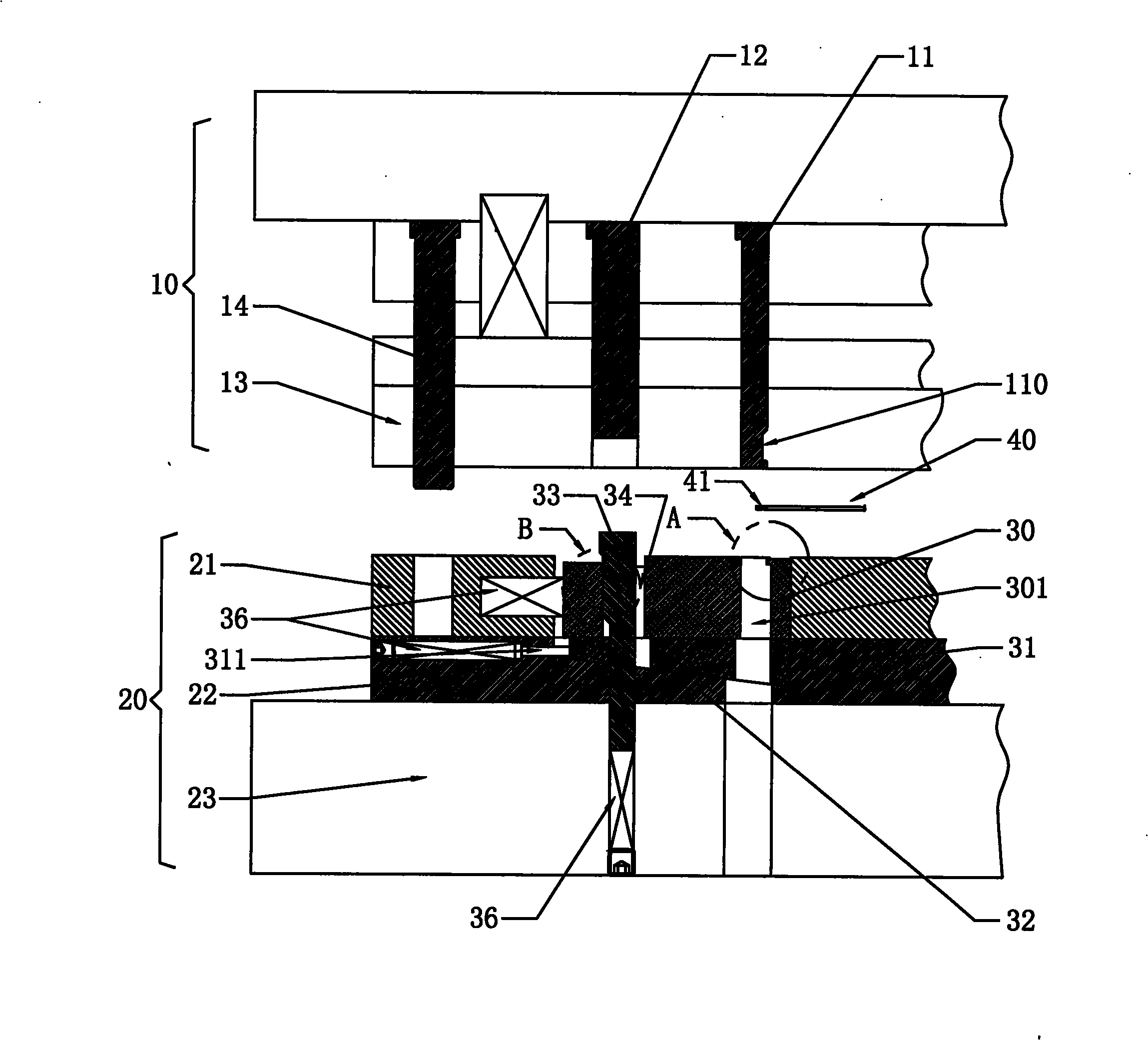
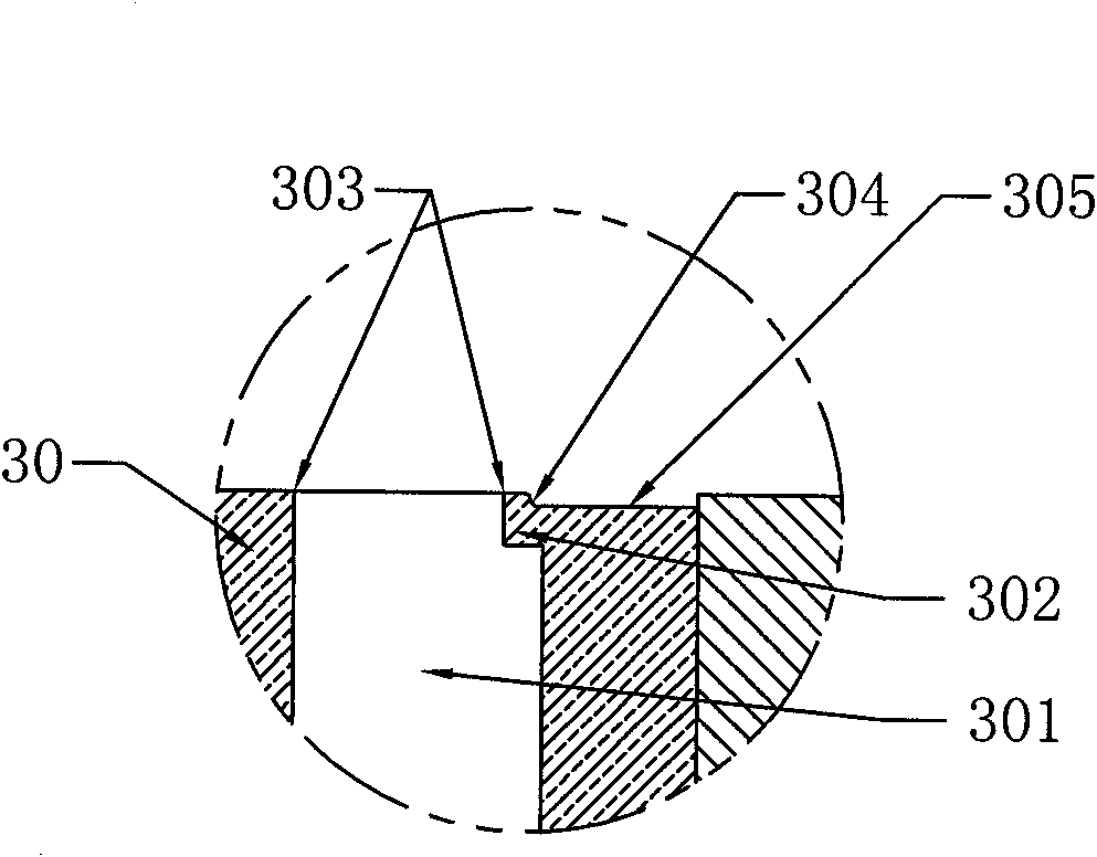
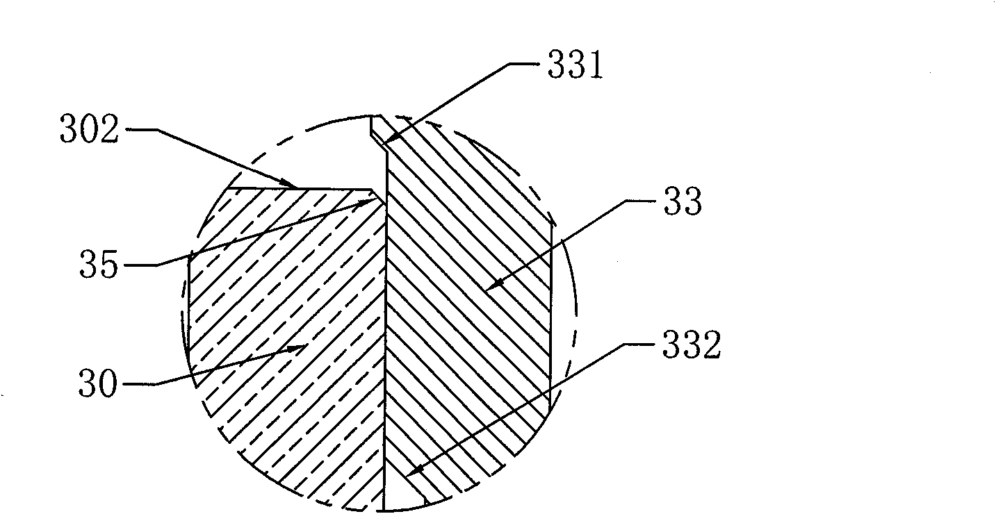
[0021] Such as Figure 1 to Figure 4 As shown, the device for synchronous punching and deburring of the continuous die of the present invention is installed in the final blanking station of the continuous die, and two punches are arranged in its upper die 10, and the lower die 20 is provided with a concave template 21 , the lower backing plate 22 and the lower mold base 23, and the lower mold 20 is provided with an insert group. The insert set includes a die slider 30 , a floating slider 31 up and down, a slider pad 32 and a wedge 33 . The slider pad 32 is placed on the upper end surface of the lower mold base 23 and embedded in the lower backing plate 22. The slider pad 32 is provided with a floating slider 31 up and down. The end face is an inclined plane of sliding fit, and the vertical sections of the up and down floating slider 31 and the slider pad 32 are right-angled trapezoids, and the hypotenuse of the up and down floating slider 31 is shorter than the hypotenuse of ...


PUM


Abstract

The invention discloses a device for synchronously blanking scraps and removing burrs for a progressive die. An insert assembly capable of sliding leftwards and rightwards is arranged at a notch at the final blanking position of the progressive die. The insert assembly comprises a female die sliding block, a sliding block cushion, an up-and-down floating sliding block and an inclined wedge, wherein the female die sliding block can move transversely and longitudinally in a female die plate; the sliding block cushion is embedded in a lower base plate; the up-and-down floating sliding block can slide along the sliding block cushion; the inclined wedge can vertically move; the upper end face of the sliding block cushion and the lower end face of the up-and-down floating sliding block are inclined planes which are in sliding fit; the female die sliding block is provided with a blanking working hole; the upper end of the blanking working hole is provided with a burr step protruding towards the inside of the hole; and the edge of the burr step is provided with a chamfer angle. Due to the adoption of the device, the problem that the scraps and connected materials of the progressive die cannot be removed so that the burrs are finally left is completely solved, the scrap blanking and the burr removal on a blanked workpiece can be completed only by once positioning, the cost of manually removing the burrs or removing the burrs by a single engineering die is saved, and the production efficiency and the product quality are greatly improved.

Description

【Technical field】 [0001] The invention relates to a device for removing laps and burrs in the field of hardware processing, in particular to a device for synchronously punching laps and removing burrs with a continuous die. 【Background technique】 [0002] The continuous die in the existing metal mold usually refers to the linear feeding direction of the punched raw material on the die, which has at least two or more stations, and is completed at different stations in one stroke of the press. Multiple stamping operations. With the development of the hardware manufacturing industry, the requirements for hardware parts are becoming more and more sophisticated, especially for the safety performance of hardware products. However, in the stamping process of the metal mold, sharp burrs often appear on the truncated surface after punching, which makes it inevitable that the operator will come into contact with the sharp burrs when the hardware parts are assembled into a product, wh...

Claims


Application Information

Patent Timeline
Patent Type & Authority Applications(China)
IPC IPC(8): B21D37/10B21D28/16
Inventor 张勇张福生
Owner SHENZHEN EVA PRECISION TECH GRP CO LTD
Why Eureka
Try Eureka