Sander

一种砂光机、联接件的技术,应用在砂光机领域,能够解决不能解决弊端等问题

Active Publication Date: 2012-01-11
TECHTRONIC POWER TOOLS TECHNOLOGY LTD
View PDF7 Cites 3 Cited by
  • Summary
  • Abstract
  • Description
  • Claims
  • Application Information

AI Technical Summary

Problems solved by technology

However, such a design also does not address the disadvantages of this configuration, such as those mentioned above

Method used


Image

  • Sander
  • Sander
  • Sander

Examples


Embodiment Construction

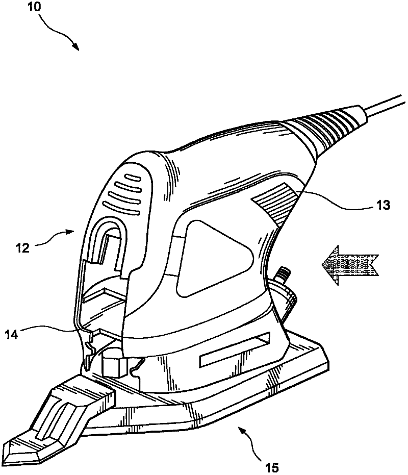
[0034] exist Figure 1 to Figure 5 The sander 10 shown in detail of the first embodiment of the invention is used for sanding inside corners and other hard-to-reach places. The sander 10 has a main body 12 including a grip portion 13 by which the main body 12 can be held by a user. At the front of the main body 12 a recess 14 is provided. The main body 12 houses a motor (not shown) and a vibration drive mechanism (not shown). A base member 15 provided below the main body 12 is fixed to the vibration driving mechanism so as to support a working member (not shown). The working member may be a sheet of sandpaper (not shown) or similar abrasive removably attached to the lower plane of the first base member 15, such as by hook and loop fasteners or adhesive.

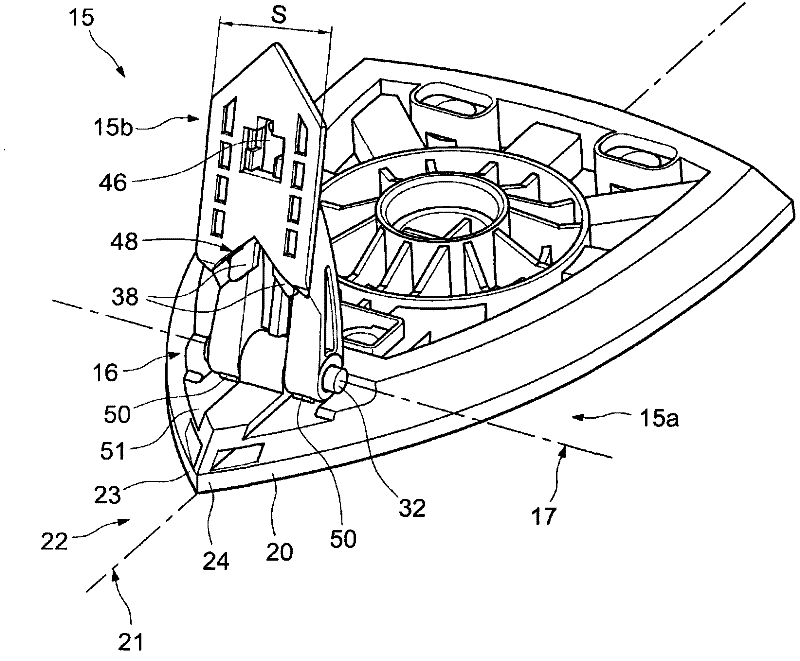
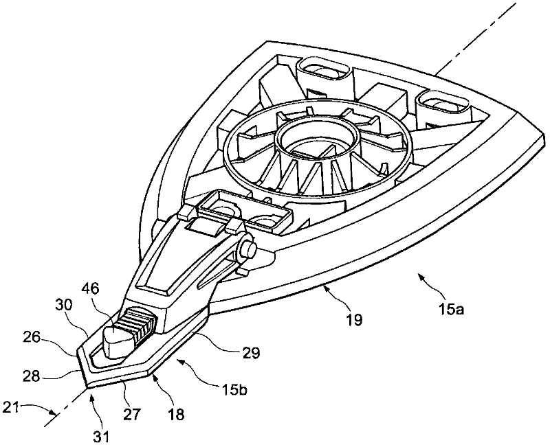
[0035] The base member 15 includes a first portion 15a directly connected to the vibration drive mechanism and a second portion 15b connected to the first portion 15a by a coupling 16 such that the first base member 15a ca...


PUM


Abstract

A sander has two abrasive-supporting base parts (15a / 15b, 215a / 215b, 315a / 315b) mounted to an oscillating drive mechanism. The base parts may support a sandpaper sheet, or the like, and are connected to one another in a manner allowing ready reconfiguration for different applications. One of the base parts is connected by a pivoting coupling (16, 216, 316) to the other for movement between extended and retracted positions. Latching means (37, 42, 238, 232, 234, 62, 63, 67, 332, 334, 83, 84, 336) releasably lock the coupling so as to hold the parts in the extended position.

Description

technical field [0001] The present invention relates to sanding machines, in particular sanding machines having an abrasive support base comprising at least two parts. Background technique [0002] A rotary or inline sander has a base that supports an abrasive sheet or consists of abrasive blocks or pads. The abrasive support base is secured to a motor-driven vibratory mechanism. Sanders can be configured to accommodate bases of different shapes (such as rectangular, triangular, or elongated fingers) for different applications, and these bases are usually secured by screw fasteners. Providing this removable base makes the sander more versatile, but the configuration is not without some drawbacks. For example, replacement operations can be time consuming and require carrying or storing replacement bases, some of which can be small parts that are easily forgotten. [0003] In addition to the entire base being detachable, it is known to provide abrasive support bases made in...

Claims


Application Information

Patent Timeline
Patent Type & Authority Applications(China)
IPC IPC(8): B24B23/00B24B23/04
CPCB24B23/04B24B23/005B24B27/00B24B27/0076
Inventor 梁希逊莫国庭
Owner TECHTRONIC POWER TOOLS TECHNOLOGY LTD
Why Eureka
Try Eureka