Gypsum dewatering and impurity removal device
A gypsum and cavity technology, applied in the field of gypsum dehydration and impurity removal devices, can solve the problems of slurry impurities, etc., and achieve the effect of good effect, convenient disassembly and washing, and strong practicability
- Summary
- Abstract
- Description
- Claims
- Application Information
AI Technical Summary
Problems solved by technology
Method used
Image
Examples
Embodiment 1
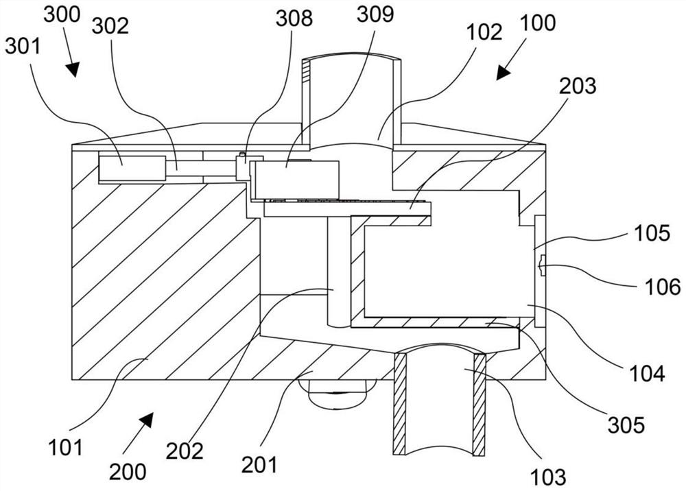
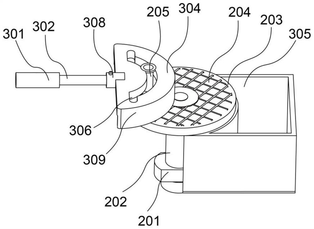
[0027] refer to Figure 1-3 , providing a schematic diagram of the overall structure of a gypsum dehydration and impurity removal device, such as figure 1 A gypsum dehydration and impurity removal device includes a frame assembly 100, including a cavity box 101, a slurry inlet 102 arranged on the top of the cavity box 101, and a slurry outlet 103 arranged at the bottom of the cavity box 101; The separation assembly 200 includes a motor 201 arranged at the bottom of the cavity casing 101, a rotating shaft 202 matched with the motor 201 and a separation disc 203 fixedly connected with the rotation shaft 202; The slide plate 301 fixedly connected to the left side wall of 101, the cleaning rod 302 that slides with the slide plate 301, the cleaning brush 304 that is arranged on one end of the cleaning rod 302 and the separation disc 203, and the storage box 305 that is arranged below the separation disc 203.
[0028] Specifically, the main structure of the present invention includ...
Embodiment 2
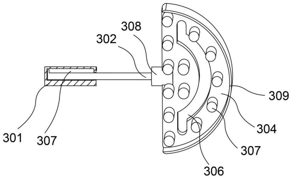
[0031] refer to Figure 1-3 , this embodiment is different from the first embodiment in that: the separation disc 203 is provided with a fine-diameter filter screen 204; 306, the bottom of the cleaning brush 304 is provided with some intersecting bristles 307; the slide plate 301 is provided with a chute 307, the end of the cleaning rod 302 near the slide plate 301 is provided with a slider, and the slide block is slidably matched with the chute 307; the cleaning brush 304 is provided with Connecting head 308, cleaning head 308 is disassembled and connected with cleaning bar 302; Storage box 305 is fixedly connected with the right side wall of cavity box body 101, and storage box 305 top and near cavity box body 101 side are provided with openings, and other structures are all with Example 1 is the same.
[0032] Specifically, the separation disc 203 is provided with a fine-diameter filter screen 204, which can filter and remove impurities more carefully on the slurry.
[00...
Embodiment 3
[0039] refer to Figure 1-4 , this embodiment is different from the above embodiments in that: the cavity box body 101 is provided with a through groove 104 matching with the opening of the storage box 305, the through groove 104 is hinged with a cleaning door 105, and the through groove 104 is provided with a hole , the cleaning door 105 is provided with a bump 106 that is snap-connected with the hole slot; the bottom of the edge of the cleaning brush 304 is provided with a scraper 309, and the width of the scraper 309 gradually decreases from top to bottom; the storage box 305 is close to the slurry outlet 103- A filter screen 310 is opened on the side; the height of the bottom of the cavity box 101 gradually decreases from both sides toward the pulp outlet 103, and other structures are the same as in Embodiment 2.
[0040] Specifically, the cavity box 101 is provided with a through groove 104 that matches the opening of the storage box 305, which is convenient for the opera...
PUM
 Abstract
Description
Claims
Application Information
 - R&D
- Intellectual Property
- Life Sciences
- Materials
- Tech Scout
- Unparalleled Data Quality
- Higher Quality Content
- 60% Fewer Hallucinations
Browse by: Latest US Patents, China's latest patents, Technical Efficacy Thesaurus, Application Domain, Technology Topic, Popular Technical Reports.
© 2025 PatSnap. All rights reserved.Legal|Privacy policy|Modern Slavery Act Transparency Statement|Sitemap|About US| Contact US: help@patsnap.com


