Liquid ejection head, liquid ejection apparatus and inkjet printing apparatus

A liquid ejection head, liquid technology, applied in the direction of printing, inking devices, etc., can solve the problems of no open suppression, deviation of ejection direction, etc.

Inactive Publication Date: 2012-01-11
FUJIFILM CORP
View PDF10 Cites 11 Cited by
  • Summary
  • Abstract
  • Description
  • Claims
  • Application Information

AI Technical Summary

Problems solved by technology

In addition, in the composition of forming one pixel by ejecting liquid droplets from a plurality of nozzles, there is such concern that regarding the deviation of the ejection direction due to manufacturing differences, there is no disclosure of a composition that suppresses the occurrence of this problem so far.

Method used


Image

  • Liquid ejection head, liquid ejection apparatus and inkjet printing apparatus
  • Liquid ejection head, liquid ejection apparatus and inkjet printing apparatus
  • Liquid ejection head, liquid ejection apparatus and inkjet printing apparatus

Examples


Embodiment Construction

[0076] Here, an inkjet head using a piezoelectric actuator is described as an example, but the present invention can also be applied to various types of inkjet heads, such as using electrostatic actuators, heat generating elements (heaters), etc. as ejection energy The inkjet head that produces the element. In addition, the present invention can also be applied to a drop-on-demand type inkjet head or a continuous jet type inkjet head. In particular, the present invention is applicable to an inkjet head based on a method using resonance inkjet, as in an inkjet head using a piezoelectric actuator.

[0077] Composition and classification of technical problems in the prior art

[0078] Before describing the embodiments of the present invention, first, the composition of an inkjet head in the prior art will be described, and related technical problems will be classified.

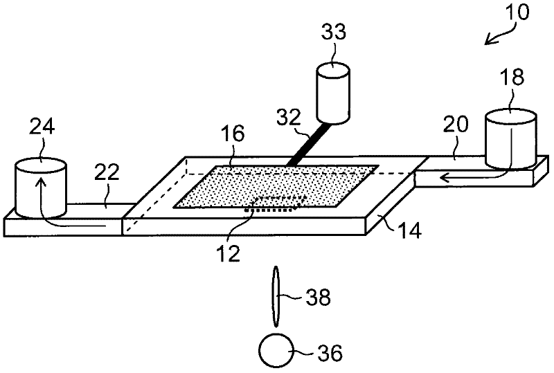
[0079] FIG. 1 is a schematic diagram showing the composition of an inkjet head in the related art using pi...


PUM


Abstract

The invention provides a liquid ejection head, a liquid ejection apparatus and an inkjet printing apparatus. The liquid ejection head has a recording element including a set of ejection elements. Each of the ejection elements includes a pressure chamber, a supply flow channel connected to the pressure chamber, an ejection energy generating device arranged correspondingly to the pressure chamber, and an ejection port connected to the pressure chamber. The ejection elements constituting the same set have identical ejection operation characteristics. The ejection energy generating devices included in the ejection elements constituting the same set are connected to a common signal wire, and are configured to be applied with the same drive signal through the common signal wire to be simultaneously driven. In the ejection elements constituting the same set, when the ejection energy generating devices are simultaneously driven, liquids are ejected from the pressure chambers through the ejection ports and deposited to a same pixel on an image formation medium in an image formation operation.

Description

technical field [0001] The present invention relates to a liquid ejection head, and more particularly, to a head structure for ejecting liquid droplets by an inkjet method, and to a liquid ejection apparatus and an inkjet printing apparatus using such a head. Background technique [0002] Japanese Patent Application Laid-Open No. 2005-035271 discloses a composition in which ink droplets ejected separately from two ink ejection units are caused to collide and combine with each other in flight, and the combined droplets are deposited on a recording medium, thereby printing at a high speed High resolution images. The two ink ejection units have mutually separated (independent) pressure chambers and piezoelectric actuators, and the ejection timing and the number of ejected ink droplets of each ejection unit are controlled. Japanese Patent Application Publication No. 06-071902 discloses a technique similar to Japanese Patent Application Publication No. 2005-035271. [0003] Jap...

Claims


Application Information

Patent Timeline
Patent Type & Authority Applications(China)
IPC IPC(8): B41J2/21B41J2/045
CPCB41J2202/11B41J2/14233B41J2/211B41J2002/14491B41J2202/12
Inventor 永岛完司
Owner FUJIFILM CORP
Why Eureka
Try Eureka