Ball-and-socket joint

A ball hinge and hinge head technology, applied in mechanical equipment, shaft installation, rotating parts resistant to centrifugal force, etc., can solve problems such as hindering the reliability of resistance pressure welding, and achieve high strength, high bending section coefficient, and cost saving. Effect

Inactive Publication Date: 2012-01-11
ZF FRIEDRICHSHAFEN AG
View PDF0 Cites 1 Cited by
  • Summary
  • Abstract
  • Description
  • Claims
  • Application Information

AI Technical Summary

Problems solved by technology

[0004] Due to the limited space between the groove of the bellows and the bead or housing edge due to the limited installation space, only Ability to use limited soldering surfaces
Conversely, making the joint widen to have an oval or rectangular cross-section more and more hinders the reliability of resistance pressure welding and seems to lead to higher weld ridges and more spatter during welding same, resulting in a larger weld pool

Method used


Image

  • Ball-and-socket joint
  • Ball-and-socket joint
  • Ball-and-socket joint

Examples


Embodiment Construction

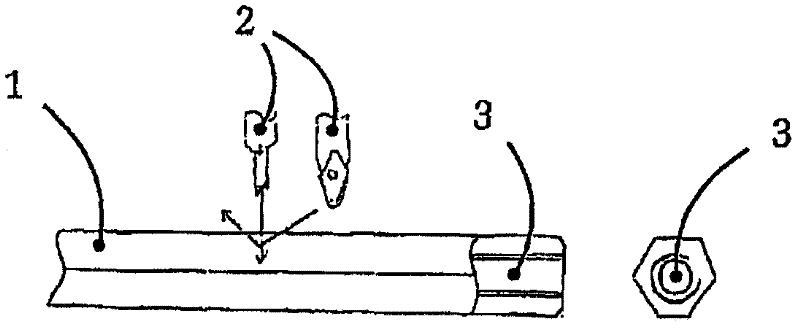
[0044] figure 1 A semi-finished product 1 for producing a ball joint handle is shown in a schematic illustration. In addition, in figure 1 Also shown are cutting or cutting tools 2 , with which the semi-finished product 1 can be cut to size to form a ball joint 5 . The substantially tubular semi-finished product 1 used here already has an internal thread 3 and, in the exemplary embodiment shown, a hexagonal outer contour 4 . During cutting to size, a flat surface can be simultaneously produced on the end side for the subsequent contact surface of the nut, for mounting the ball joint, for example, on a steering rod. If the semi-finished product 1 itself does not have an internal thread, the internal thread 3 can be produced in a simple manner during cutting to size, in particular with the same clamping, after possible flattening of the end face.

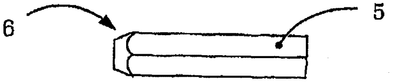
[0045] figure 2 shows the basis figure 1 Ball joint shank 5 in the form of a cut-to-size semi-finished product which has been ...


PUM


Abstract

The joint has a shaft (5) and a ball joint (7,11) frictionally welded with one another as separate components in an electrical resistance manner. A spigot (8) is formed at the ball joint, and the shaft is welded with the spigot. The shaft is formed with two fork ends in a region of a connection with the ball joint. The shaft is formed as a tubular semi-finished material with an integrated screw thread (3). A chamfer is welded with the ball joint. A weld seam (9) is moved from a surface area of the ball joint into a region of a transition between the spigot and the chamfer at the shaft. The joint provided in the invention has the advantages of low manufacturing cost, reliable manufacture, small stress concentration effects and high fatigue strength, especially low manufacturing cost and high part strength.

Description

technical field [0001] The invention relates to a ball joint according to claim 1 or the preamble of claim 4 , which has a ball joint head and a shaft, wherein the shaft and ball joint head are welded together. Background technique [0002] Ball joints with a separately produced ball joint head and ball joint shank are known from the prior art, wherein the ball joint head and the ball joint shank are welded together to form the ball joint. In this known ball joint, the ball joint shank is usually welded directly to the ball joint head. However, such welds, which are mostly obtuse, have various disadvantages. Due to the sharp cross-sectional mutation between the wall and the shank of the ball joint, where the cross-sectional mutation also coincides with the position of the weld, a relatively strong stress increase is generated, which in turn creates a potential stress concentration effect. [0003] In addition, in order to form the weld seam, a certain surface area is requ...

Claims


Application Information

Patent Timeline
Patent Type & Authority Applications(China)
IPC IPC(8): F16C11/06
CPCF16C2226/36F16C11/0685F16C2220/46F16C11/0695
Inventor M・韦勒丁格H・雷克斯L・科比尔
Owner ZF FRIEDRICHSHAFEN AG
Why Eureka
Try Eureka