Drum brake

A technology for drum brakes and brake shoes, applied in the direction of hydraulic drum brakes, slack adjusters, etc., can solve the unfavorable problems of drum brake reliability, etc., and achieve the effect of fewer structures, reduced assembly processes, and simple assembly

Inactive Publication Date: 2012-01-11
BYD CO LTD
View PDF9 Cites 15 Cited by
  • Summary
  • Abstract
  • Description
  • Claims
  • Application Information

AI Technical Summary

Problems solved by technology

[0006] Traditional drum brakes have the following problems: Since the shifting action of the paddle is based on a tooth, the gap se

Method used


Image

  • Drum brake
  • Drum brake
  • Drum brake

Examples


Embodiment Construction

[0027] In order to make the technical problems, technical solutions and beneficial effects solved by the present invention clearer, the present invention will be further described in detail below in conjunction with the accompanying drawings and embodiments. It should be understood that the specific embodiments described here are only used to explain the present invention, not to limit the present invention.

[0028] Specific embodiments of the present invention will be described in detail below with reference to the accompanying drawings. Herein, the same reference numerals denote the same constituents.

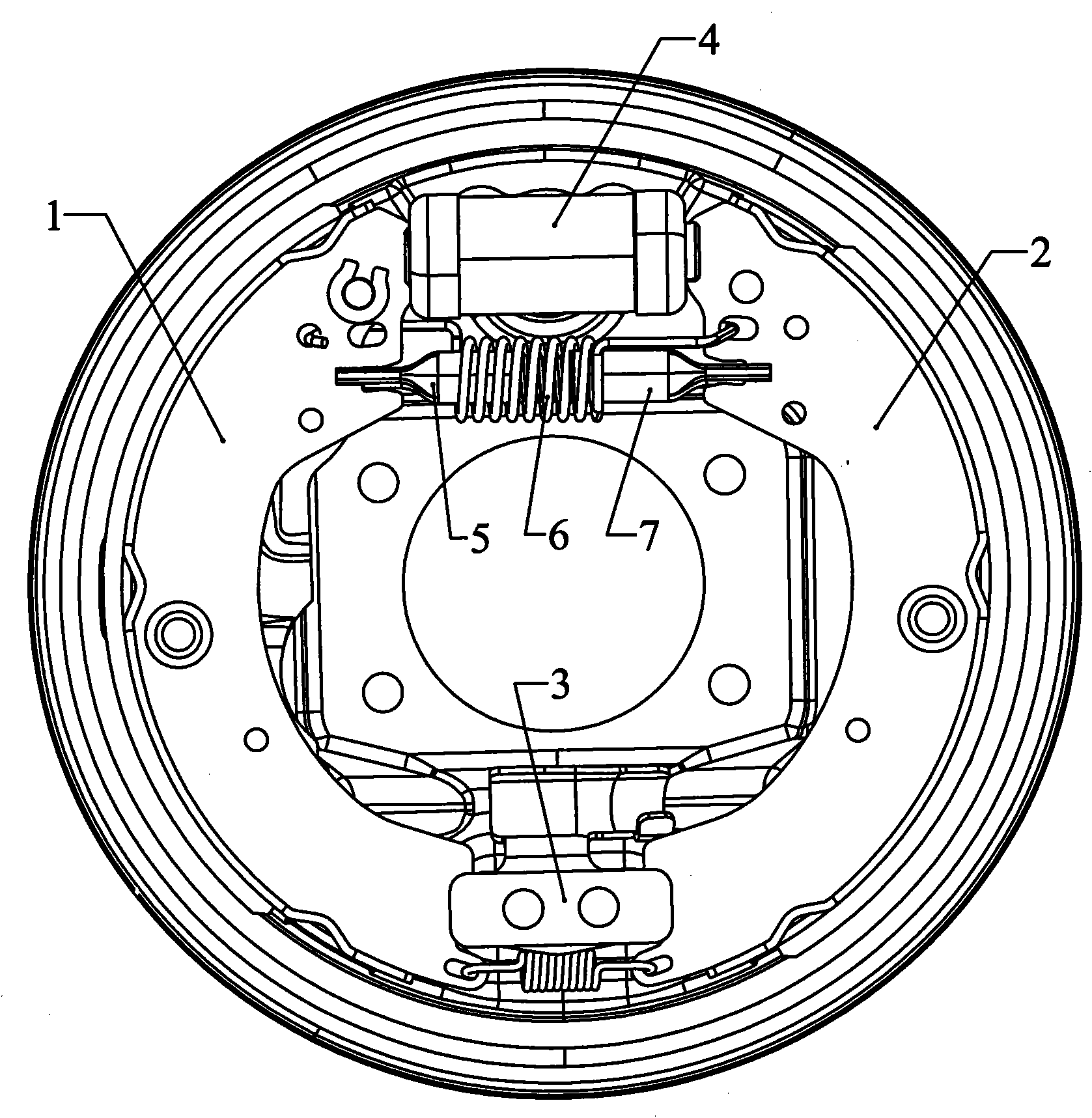
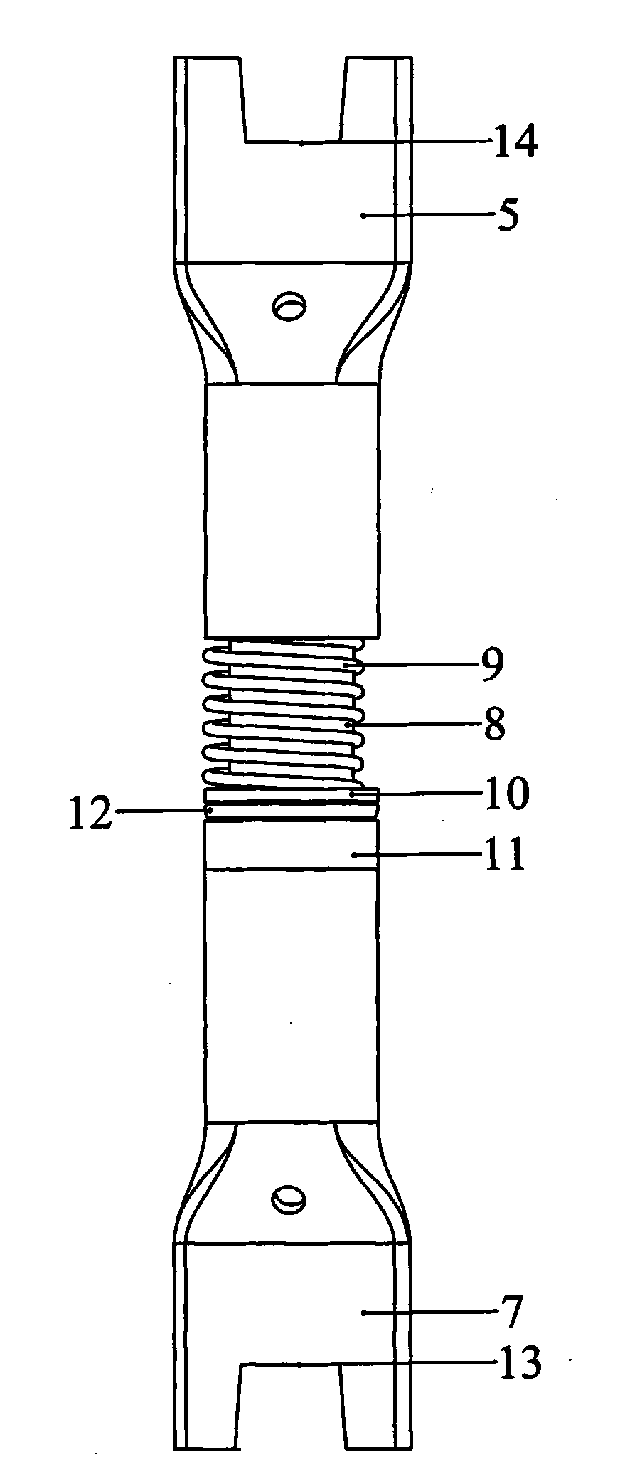
[0029] Such as figure 1 and 5 As shown, the drum brake of the present invention includes a brake drum (not shown), a first brake shoe 1, a second brake shoe 2, a brake shoe support block 3, a piston 4 of a brake wheel cylinder, a return Spring 6. Both the first brake shoe 1 and the second brake shoe 2 have friction plates. Among them, during the braking process of the ...


PUM


Abstract

The invention provides a drum brake, which comprises a brake drum, a first brake shoe, a second brake shoe, a return spring and a gap self-adjustment mechanism, wherein the two ends of the return spring are hooked on the first brake shoe and the second brake shoe respectively; the gap self-adjustment mechanism is connected between the first brake shoe and the second brake shoe and comprises a screw sleeve, a screw and a pivotal carrier; a first section of the screw is provided with external threads; the screw sleeve is provided with internal threads; the external threads and the internal threads form a self-lock thread pair; the internal threads are in clearance fit with the external threads; a second section of the screw is pivotally connected with the pivotal carrier; and the gap self-adjustment mechanism also comprises a pushing component for separating the screw sleeve away from the screw. The drum brake can realize continuous and stepless adjustment of gaps produced by wear; and the reliability of brake and the safety performance of a vehicle are enhanced. Since the number of the parts of the drum brake is much less than that of the parts of the conventional structure, the assembly is easy, the cost can be reduced, and the assembly processes are reduced.

Description

technical field [0001] The invention belongs to the technical field of vehicle braking. Specifically, the present invention relates to a drum brake, especially a drum brake with self-adjusting clearance function. Background technique [0002] As we all know, when braking, the brake shoe of the drum brake spreads outwards and rubs against the inner side of the brake drum to achieve the purpose of driving brake. Since the drum brake realizes the braking of the vehicle by friction, it will inevitably cause the wear of the brake drum and the friction plate, which will inevitably lead to an increase in the gap between the brake drum and the friction plate. [0003] Since the wear of the brake drum and the friction plate will cause the brake gap to increase, the brake response time will increase accordingly, which will increase the driving risk. For this reason, the early drum brakes of vehicles used manual adjustment of the gap caused by wear. When the vehicle traveled for a ce...

Claims


Application Information

Patent Timeline
IPC IPC(8): F16D51/24F16D65/56
Inventor 李小永周宇
Owner BYD CO LTD
Why Eureka
Try Eureka