Valve

A technology for valves and valve stems, applied to valve devices, cocks including cut-off devices, engine components, etc., can solve problems such as insufficient flow control, inability to lock valves, complex structure of locking devices, etc., and achieve convenient operation and simple structure Effect

Inactive Publication Date: 2012-01-11
施锦成
View PDF0 Cites 3 Cited by
  • Summary
  • Abstract
  • Description
  • Claims
  • Application Information

AI Technical Summary

Problems solved by technology

[0002] In the existing lock control valve, a lock core is set in the valve stem installation sleeve, which can only lock the valve in the open state, or can only lock the valve in the closed state, but cannot lock the valve according to the actual flow required by the valve. Moreover, the structure of the locking device of this valve is very complicated.
However, some valves can control the flow by themselves, but in some harsh environments, the flow control is often not in place
For example, under the condition of vibration, some valves will rotate automatically under the action of strong vibration, which seriously affects the flow control, sometimes causing irreparable consequences.

Method used


Image

  • Valve
  • Valve

Examples


Embodiment Construction

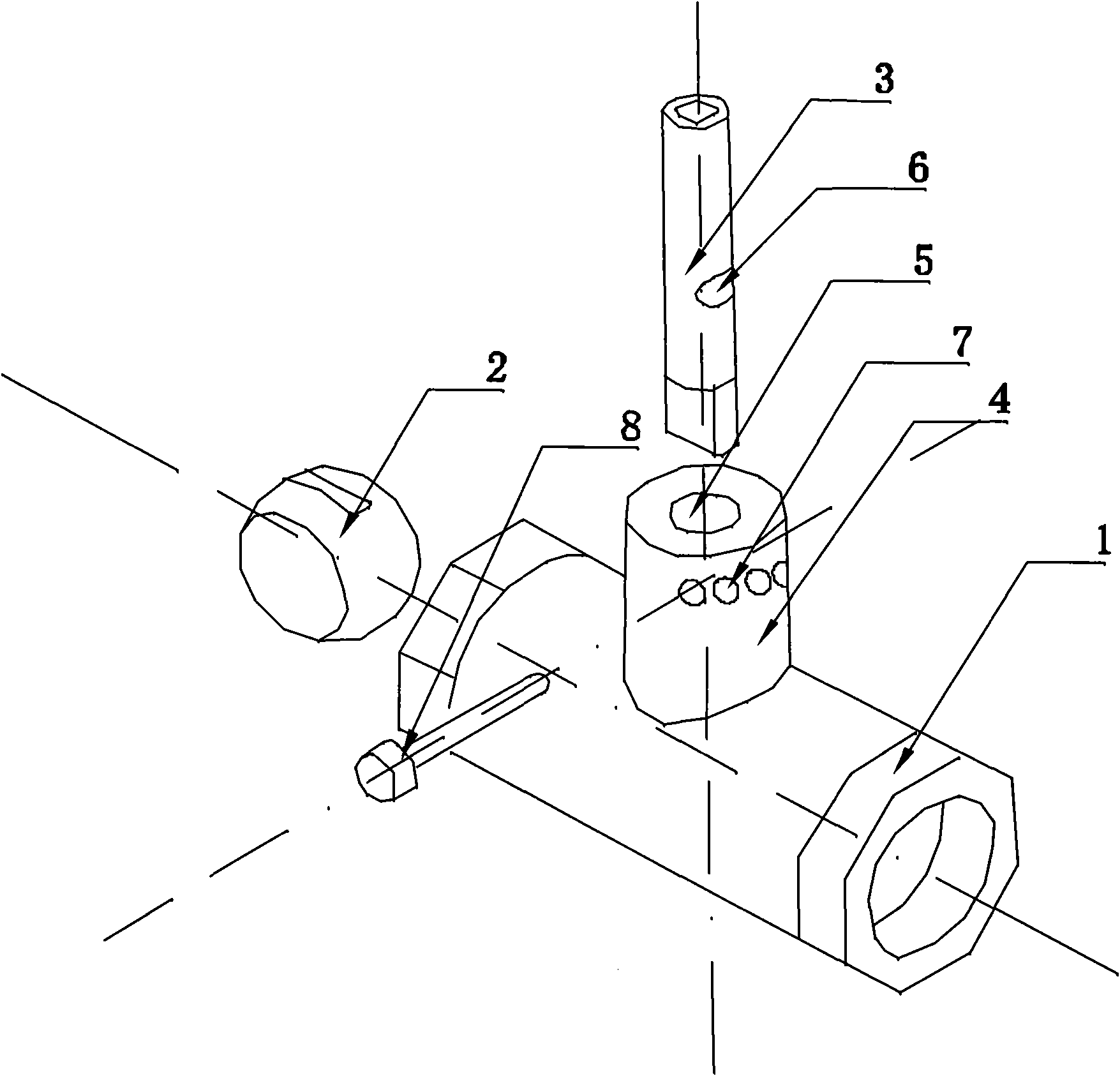
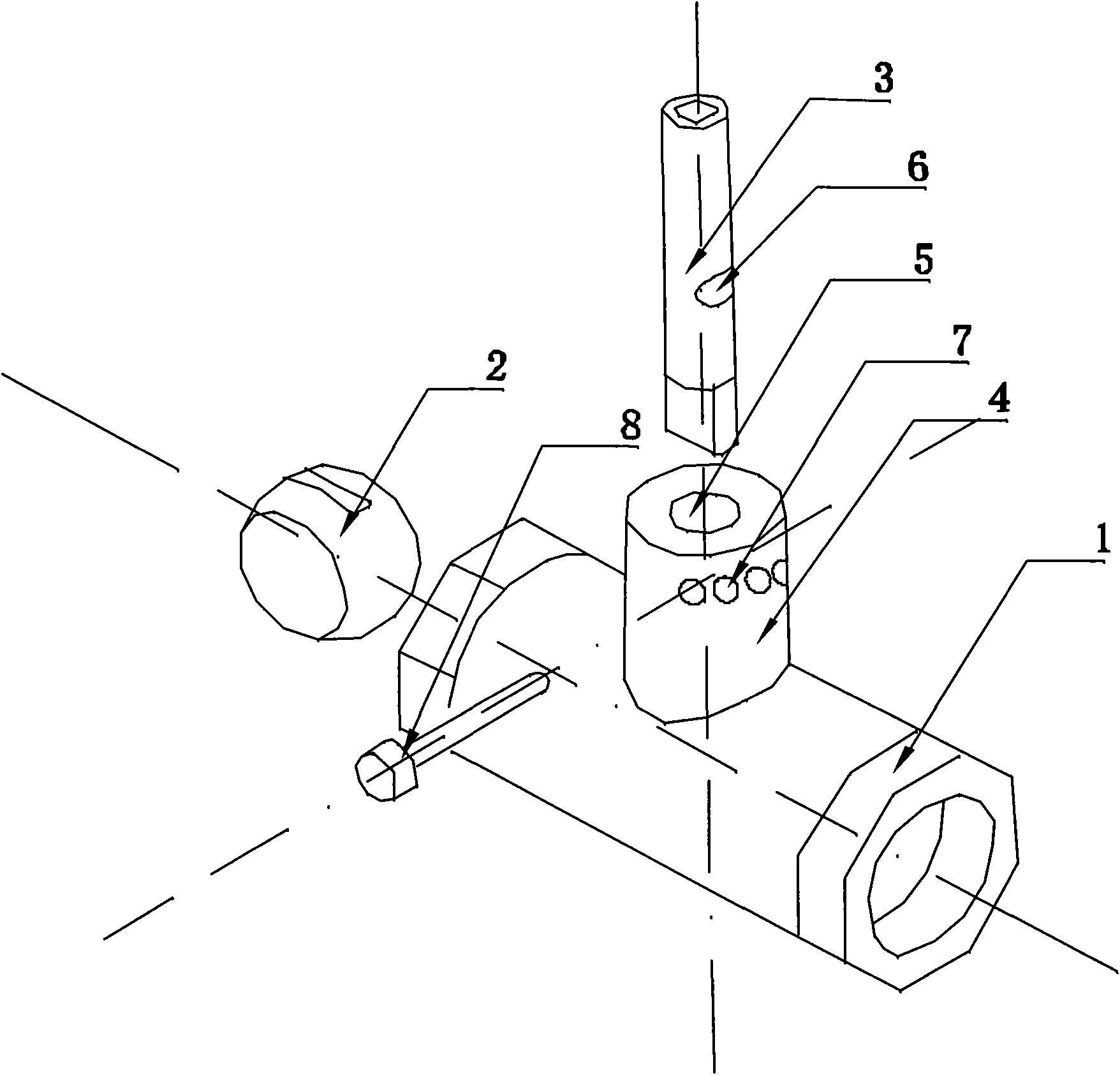
[0009] Such as figure 1 As shown, a valve includes a valve body 1, a valve core 2, a valve stem 3, a valve stem mounting sleeve 4 and a valve stem mounting channel 5 formed by an internal cavity of the valve stem mounting sleeve 4, and the valve stem 3 is installed on the valve stem In the sleeve 4 and connected with the valve core 2, a groove 6 is provided on the valve stem 3, and the groove 6 is through in the longitudinal direction of the valve stem. The corresponding groove is on a quarter of the circumference of the valve stem mounting sleeve 4. 6 is provided with a plurality of through holes 7 at a height, and the longitudinal axis of the through hole 7 is approximately perpendicular to the longitudinal axis of the valve stem mounting channel 5. When the flow rate of the valve needs to be locked at a certain value, the valve stem 3 The groove 6 is rotated to communicate with the corresponding through hole 7, and the through hole 7 is provided with a plug 8 that prevents t...


PUM


Abstract

The invention relates to a valve, which comprises a valve body, a valve core, a valve rod, a valve rod mounting sleeve and a valve rod mounting passage, wherein the valve rod mounting passage is formed by an internal cavity of the valve rod mounting sleeve; the valve rod is arranged in the valve rod mounting sleeve, is connected with the valve core and is provided with a groove; and the groove runs through in the direction of the longitudinal axis of the groove. The valve is characterized in that: one fourth circumference of the valve rod mounting sleeve is provided with a plurality of through holes corresponding to the height of the groove; the longitudinal axes of the through holes are approximately perpendicular to the longitudinal axis of the valve rod mounting passage; when the flow rate of the valve is required to be locked at a certain value, the groove on the valve rod can be turned to be communicated with a corresponding through hole; and a device for preventing the valve rod from rotating is arranged in the through hole and penetrates through the through hole to be engaged with the groove on the valve rod. The valve has the advantages of simple structure, convenience in operation and capability of controlling and locking the flow rate.

Description

Technical field [0001] The invention relates to a valve. Background technique [0002] The existing lock control valve is equipped with a lock core in the valve stem installation sleeve, which can only lock the open state of the valve, or can only lock the closed state of the valve, but cannot lock the valve according to the actual flow rate required by the valve. Moreover, the structure of the locking device of this valve is very complicated. However, some valves can control the flow by themselves, but in some harsh environments, the flow control is often not in place. For example, under vibration conditions, some valves will rotate on their own under strong vibration, which will seriously affect the flow control and sometimes cause irreparable consequences. Summary of the invention [0003] The purpose of the present invention is to provide a valve with a simple structure and easy operation that can be controlled and can lock the flow. [0004] The technical solution adopted by...

Claims


Application Information

Patent Timeline
IPC IPC(8): F16K37/00F16K5/06
Inventor 施锦成
Owner 施锦成
Why Eureka
Try Eureka