
Coil rack for electromagnetic switch and method for winding coils

An electromagnetic switch and coil winding technology, which is applied in coil manufacturing, inductance/transformer/magnet manufacturing, coils, etc., can solve the problems of increased manufacturing costs of starters, insufficient use of the magnetic field force of metal coils, and many metal wires, etc., to achieve Overall weight reduction, reduction in coil consumables, and reduction in the number of coil turns

Inactive Publication Date: 2012-01-11
SHANGHAI VALEO AUTOMOTIVE ELECTRICAL SYST
View PDF5 Cites 5 Cited by
  • Summary
  • Abstract
  • Description
  • Claims
  • Application Information

AI Technical Summary

Problems solved by technology

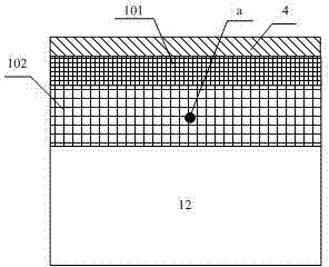
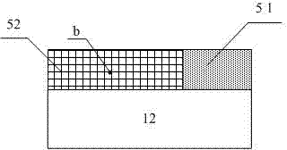
Such a switch coil 5 is designed according to a closed magnetic circuit, but after the key switch is turned on, the magnetic circuit of the movable iron core and the electromagnetic switch is in an open state, so that the magnetic field force of the metal coil does not fully play like this. The consumption of more metal wires will lead to an increase in the overall manufacturing cost of the starter

Method used


Image

  • Coil rack for electromagnetic switch and method for winding coils
  • Coil rack for electromagnetic switch and method for winding coils
  • Coil rack for electromagnetic switch and method for winding coils

Examples


Embodiment Construction

[0021] A bobbin and a coil winding method according to a specific embodiment of the present invention will be described in detail below with reference to the accompanying drawings. However, the present invention should be understood as not limited to such embodiments described below, and the technical idea of ​​the present invention can be implemented in combination with other known technologies or other technologies having the same functions as those known technologies.

[0022] In the following description, in order to clearly show the structure and working method of the present invention, many directional words will be used to describe, but "front", "rear", "left", "right", "outer", "inner" should be used ", "outward", "inward", "axial", "radial" and other terms are to be understood as convenient terms, and should not be understood as limiting terms. In addition, the term "first layer" used in the following description mainly refers to the layer of the coil close to the cor...


PUM


Abstract

The invention aims to provide a novel coil rack for an electromagnetic switch. The coil rack comprises a first baffle plate, a second baffle plate, a coil drum and two half-moon-shaped baffle plates. The coil winding mode in the prior art can be changed by utilizing the coil rack, and the excitation capability of coils can be improved.

Description

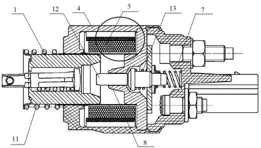
[0001] technical field [0002] The invention relates to the technical field of starters for automobile engines and other engines, in particular to a coil former for an electromagnetic switch and a coil winding method. [0003] Background technique [0004] The starter is composed of three parts: electromagnetic operating mechanism, DC motor and transmission mechanism. Such as figure 1 as shown in figure 1 It is an electromagnetic switch structure of a starter in the prior art. The electromagnetic switch structure of the starter is mainly composed of a switch housing 4, a switch coil 5, a static contact seat 7, a static iron core 8, a moving contact 12, a moving iron core 1, a maintenance spring 13, and a return spring 11. The switch coil 5 in the electromagnetic switch is composed of an attracting coil and a holding coil. The turns of the two coils are equal and the first ends are connected together for a terminal to lead out. The first end of the attracting coil is ...

Claims


Application Information

Patent Timeline
Patent Type & Authority Applications(China)
IPC IPC(8): H01H50/44H01F5/02H01F41/06H01F41/098
Inventor 刘增岗
Owner SHANGHAI VALEO AUTOMOTIVE ELECTRICAL SYST
Learn More