
A direct-boost self-varying excitation switched reluctance generator converter system

A switched reluctance and direct boost technology, which is applied in the direction of controlling the generator through the change of the magnetic field, controlling the generator, converting DC power input to DC power output, etc., can solve problems such as reduced reliability, interference, and unstable excitation voltage , to achieve the effects of high reliability, simple control and high device utilization

Active Publication Date: 2021-01-08
浙江知多多网络科技有限公司
View PDF6 Cites 0 Cited by
  • Summary
  • Abstract
  • Description
  • Claims
  • Application Information

AI Technical Summary

Problems solved by technology

[0006] The excitation power sources of the switched reluctance generator converter system are generally divided into two types: separate excitation and self-excitation. Although the external excitation mode has stable power supply, it often needs to use batteries, which require frequent maintenance, and the reliability is also reduced. Self-excitation mode does not have this problem, but the traditional self-excitation mode without isolation often has the dual problems of being disturbed by the output side of the power generation, making the excitation voltage unstable, and causing interference to the output side of the power generation in reverse

Method used


Image

  • A direct-boost self-varying excitation switched reluctance generator converter system

Examples


Embodiment Construction

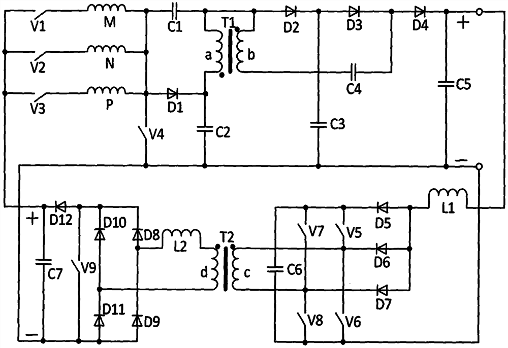
[0021] In this embodiment, a direct-boost self-variable excitation switched reluctance generator converter system, the circuit structure of the converter system is as follows figure 1As shown, it consists of the first switching tube V1, the second switching tube V2, the third switching tube V3, the fourth switching tube V4, the fifth switching tube V5, the sixth switching tube V6, the seventh switching tube V7, the eighth switching tube Tube V8, ninth switch tube V9, first phase winding M, second phase winding N, third phase winding P, first capacitor C1, second capacitor C2, third capacitor C3, fourth capacitor C4, fifth capacitor C5, sixth capacitor C6, seventh capacitor C7, first diode D1, second diode D2, third diode D3, fourth diode D4, fifth diode D5, sixth and second Diode D6, seventh diode D7, eighth diode D8, ninth diode D9, tenth diode D10, eleventh diode D11, twelfth diode D12, first The transformer T1, the second transformer T2, the first inductor L1, and the seco...


PUM


Abstract

A direct-boost self-varying excitation switched reluctance generator converter system, consisting of nine switch tubes, three-phase windings, seven capacitors, twelve diodes, two transformers, and two inductors, using the least number of switch tubes , which solves the problem of achieving different high voltage outputs under certain conditions while the windings of each phase of the switched reluctance generator are excited and generating power. The current is cut off automatically at the end of the power generation, with high efficiency and high device utilization. Under the variable excitation voltage structure, the excitation voltage can be continuously adjusted and the output of different excitation voltage ranges can be realized under certain conditions. The second transformer plays a comprehensive role of isolation, voltage transformation, and protection of the stability of the excitation power. The current at the input end of the variable excitation circuit is continuous. , less interference to the output end of the power generation, taking into account the enhanced excitation function, the whole system has high utilization rate, high reliability, low loss, low cost, and strong flexibility and adaptability: it is suitable for high-speed switched reluctance generator systems driven by various powers field application.

Description

technical field [0001] The invention relates to the field of switched reluctance motor systems, in particular to a switched reluctance generator converter system with direct voltage boosting, less switch tubes, and self-excitation variable excitation, and a control method thereof. Background technique [0002] In the field of switched reluctance motor system, the converter system is the core key part of its stable and efficient operation. In the switched reluctance motor converter system, the number of switch tubes directly determines the complexity of the control, the size of the switching loss, the switching Protection capacity, etc. Naturally, under the premise of completing the same function, the less switching tubes are used, the better. Generally speaking, the cost and control complexity will be reduced, and the loss will be reduced to improve efficiency. [0003] As a switched reluctance generator, the power generated by it in the traditional way, that is, the power g...

Claims


Application Information

Patent Timeline
Patent Type & Authority Patents(China)
IPC IPC(8): H02P9/30H02P9/38H02M3/335
CPCH02M3/33576H02P9/305H02P9/38H02M1/0048Y02B70/10
Inventor 孙冠群邬舒宁浪潮
Owner 浙江知多多网络科技有限公司
Learn More