Method and system for calibrating antenna of distributed base station
What is AI technical title?
AI technical title is built by Patsnap AI team. It summarizes the technical point description of the patent document.
A technology of distributed base station and calibration method, applied in the field of wireless communication system, can solve the problems of increasing hardware cost, inconsistent hardware structure of OFDM system, etc., and achieve the effect of good performance
Active Publication Date: 2014-09-10
ZTE CORP
View PDF3 Cites 0 Cited by
Summary
Abstract
Description
Claims
Application Information
AI Technical Summary
This helps you quickly interpret patents by identifying the three key elements:
Image
Click on the blue label to locate the original text in one second.
Reading with bidirectional positioning of images and text.
Examples
Embodiment 1
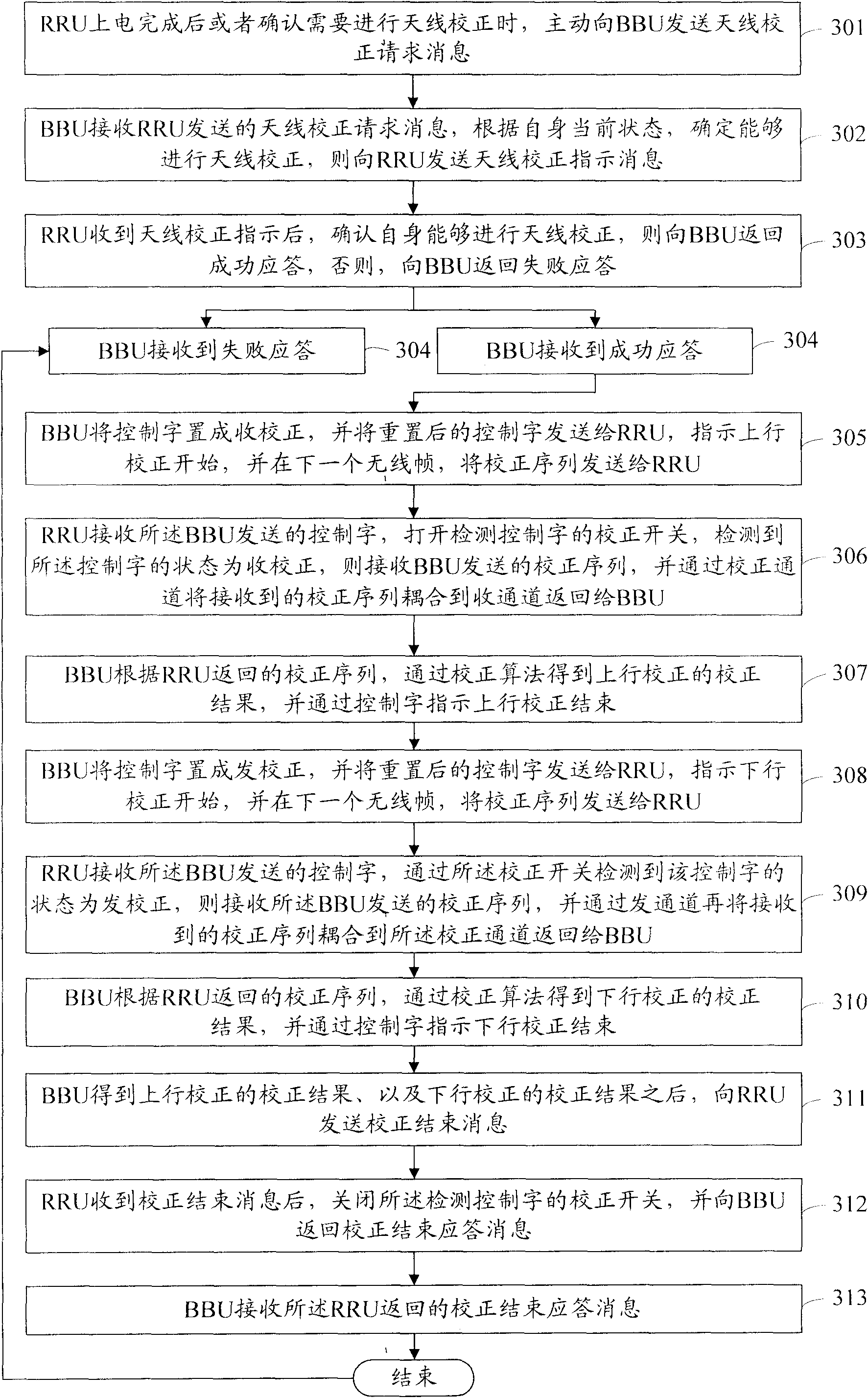
[0070] refer to image 3 , Figure 4 As shown, when the RRU side actively initiates antenna calibration, the distributed base station antenna calibration process of the present invention, the specific process is as follows:
[0071] Step 301: After the RRU is powered on or when it is confirmed that antenna calibration is required, actively send an antenna calibration request message to the BBU;
[0072] Step 302: The BBU receives the antenna calibration request message sent by the RRU, determines that the antenna calibration can be performed according to its current state, and sends an antenna calibration instruction message to the RRU;
[0073] Step 303: After receiving the antenna calibration instruction, the RRU confirms that it can perform antenna calibration, and then returns a success response to the BBU, otherwise, returns a failure response to the BBU;
[0074] Step 304: If the BBU receives a successful response, it initiates antenna calibration and proceeds to step ...
Embodiment 2
[0088] Such as Figure 5 , 6 As shown, when the antenna calibration is actively initiated by the RRU side, the antenna calibration process of the present invention, the specific process is as follows:
[0089] Step 501: The BBU needs to perform antenna calibration according to its current state, and then sends an antenna calibration indication message to the RRU;
[0090] When the BBU confirms that its own initialization, delay measurement, or cell establishment is complete, it needs to perform antenna calibration.
[0091] Step 502: After receiving the antenna calibration instruction sent by the BBU, the RRU confirms that it can perform antenna calibration, and if so, returns a success response to the BBU, otherwise, returns a failure response to the BBU;
[0092] Specifically, the RRU can perform antenna calibration only when it completes initialization, power calibration, and delay measurement, and the configuration of the corresponding cell is also completed.
[0093] S...
PUM
Abstract
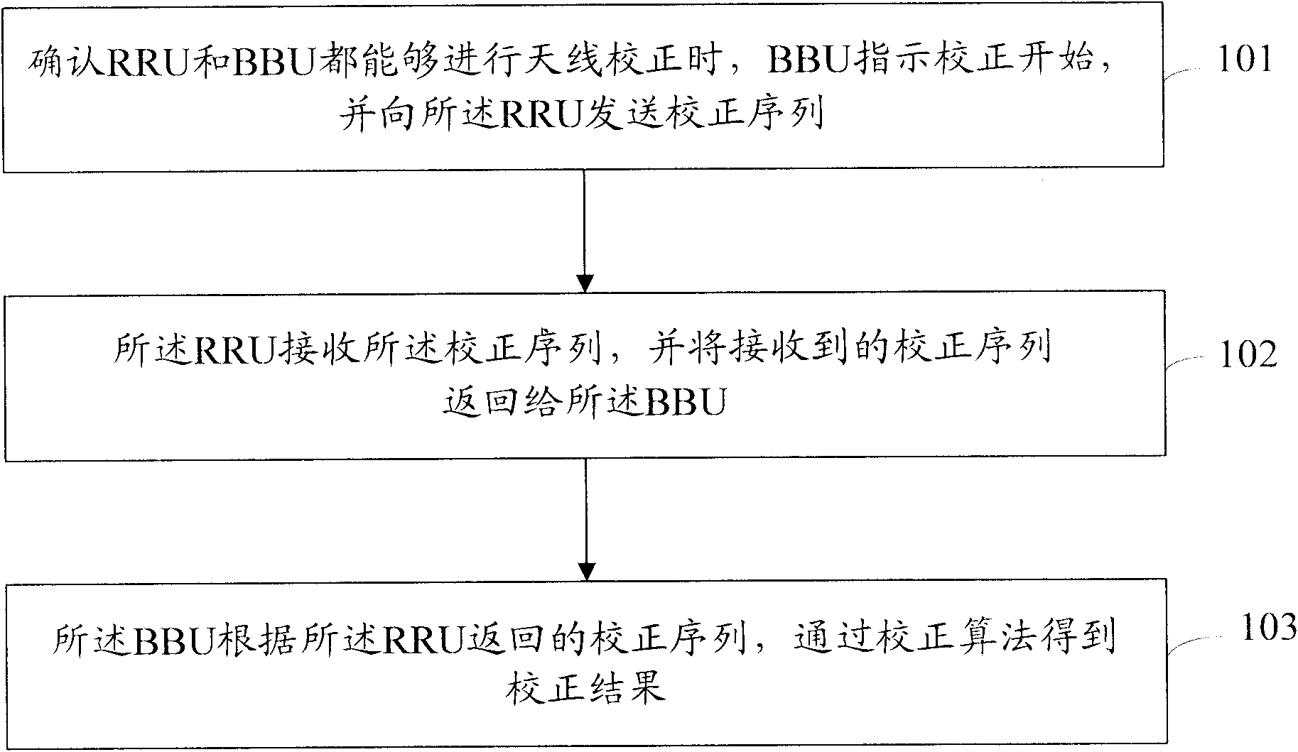
A method for calibrating an antenna of a distributed base station is disclosed by the present invention. The method includes the following steps: when confirming that both a Remote Radio frequency Unit (RRU) and a Base Band Unit (BBU) can perform antenna calibration, the BBU indicates the beginning of the calibration and sends a calibration sequence to the RRU (101); the RRU receives the calibration sequence and returns the received calibration sequence to the BBU (102); the BBU obtains a calibration result according to the calibration sequence returned from the RRU by using a calibration algorithm (103). Further, a system for calibrating an antenna of a distributed base station is also disclosed by the present invention. The present invention realizes the antenna calibration process by the interaction between the BBU and the RRU, thus realizing frequency domainantenna calibration in an Orthogonal Frequency Division Multiplex (OFDM) system. With the method, the difference of amplitude and phase among sub-carriers or sub-carrier groups in the OFDM system can be compensated effectively, and better performance for realizing beam forming function of the OFDM system can be provided.
Description
technical field [0001] The present invention relates to a wireless communication system based on Orthogonal Frequency Division Multiplexing (OFDM, Orthogonal Frequency Division Multiplexing) technology, in particular to an antenna calibration method and system for a distributed base station. Background technique [0002] The distributed base station equipment consists of a base band unit (BBU, Base Band Unit) and a radio frequencyremote unit (RRU, Remote RF Unit). It is a combination of base stations that can be flexibly distributed. The BBU) interface is connected to the BBU. [0003] In order to ensure the correctness and reliability of beamforming, the antenna array must be calibrated to reduce the amplitude and phase errors of each channel of the antenna array. Therefore, the study of antenna correction technology has very important practical significance. [0004] In the smart antenna system, many uncertain factors lead to array errors in the real antenna array manif...
Claims
Application Information
Patent Timeline
Application Date:The date an application was filed.
Publication Date:The date a patent or application was officially published.
First Publication Date:The earliest publication date of a patent with the same application number.
Issue Date:Publication date of the patent grant document.
PCT Entry Date:The Entry date of PCT National Phase.
Estimated Expiry Date:The statutory expiry date of a patent right according to the Patent Law, and it is the longest term of protection that the patent right can achieve without the termination of the patent right due to other reasons(Term extension factor has been taken into account ).
Invalid Date:Actual expiry date is based on effective date or publication date of legal transaction data of invalid patent.

