Computer equipment
A computer and equipment technology, applied in the field of computer hardware, can solve problems such as the insufficiency of technology or products, and achieve the effect of slowing down symptoms and preventing them from appearing.
- Summary
- Abstract
- Description
- Claims
- Application Information
AI Technical Summary
Problems solved by technology
Method used
Image

Examples
Embodiment 1
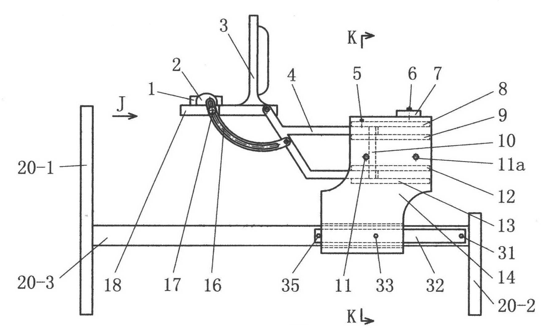
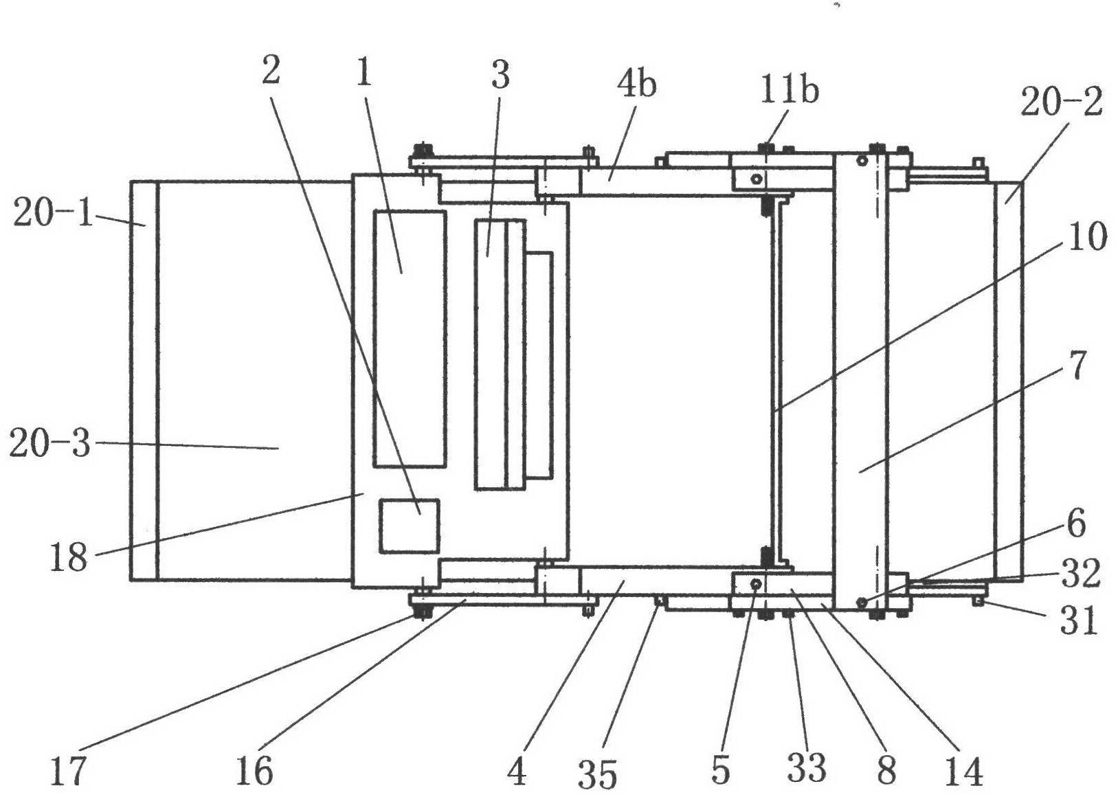
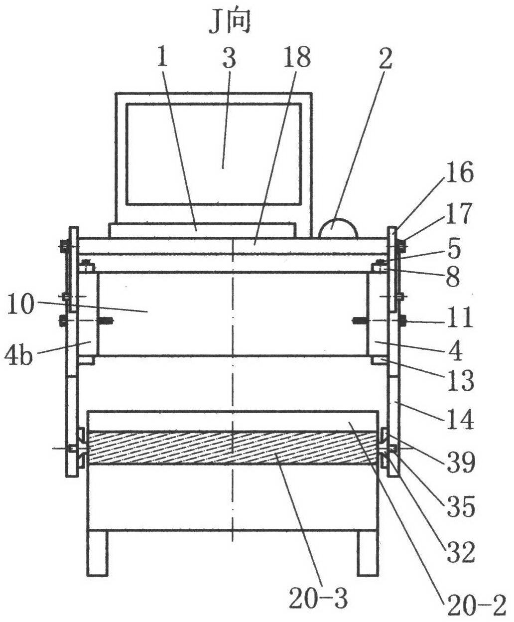
[0117] combine Figure 1 to Figure 8 Be explained. figure 1 It is one of the schematic diagrams of the equipment of the present invention; figure 2 yes figure 1 top view of image 3 yes figure 1 J direction view in ; Figure 4 yes figure 1 K-K cross-sectional view; Figure 5 yes Figure 4 Partial enlarged view of XI in the center, the magnification ratio is 3:1; Figure 6 is a three-dimensional schematic diagram of the platen; Figure 7 is a three-dimensional schematic diagram of the rear side panel; Figure 8 It is a three-dimensional schematic diagram of a part of the structure, in which there are platen, support mechanism, support bar and rear side plate, etc. drawn in the figure.
[0118] The inventive devices in this embodiment are introduced respectively as follows.
[0119] 1. Bed 20.
[0120] The bed 20 in this embodiment is mainly composed of three parts, namely: a front bed sheet 20-1, a rear bed sheet 20-2 and a bed body 20-3. The surroundings of the b...
Embodiment 2
[0154] Embodiment 2 introduces a second track mechanism that is not exactly the same as Embodiment 1.
[0155] In this embodiment, the second track mechanism includes: a left track assembly and a right track assembly; each track assembly includes: a dovetail track 32, a pair of long rods, a front limit rod 35, a rear limit Rod 31.
[0156] The dovetail track 32 is a special-shaped cylinder; the cross-sectional shape of the dovetail track 32 of the special-shaped cylinder includes: the top of a straight line, two straight line sides that are symmetrical and obliquely arranged; the distance between the two straight line sides is the top Outsole is small.
[0157] In a pair of long rods 39, there is an interval between one long rod and the other long rod, and the opposite faces of the two long rods are inclined planes, that is, a hollow trapezoidal space is formed between the two long rods. The cross-sectional shape of the trapezoidal space not only coincides with the cross-sec...
Embodiment 3
[0163] The mouse in the prior art can only be used normally when the bearing surface of the carrier is horizontal; , in these cases, if the operator once lets go, the mouse of the prior art will fall off and cannot continue to be used normally.
[0164] The mouse described in this embodiment, no matter whether the platen 18 is horizontally upward, or inclined at a large angle, vertically, or downwardly, it can reliably attract the mouse without falling down. , to ensure normal use; in addition, there is a gap layer between the lower layer of the bottom of the mouse and the relative body, and a plurality of small balls are also rotating when the mouse moves, so the mouse can be moved flexibly, freely and as one likes.
[0165] The following combination Figure 13 to Figure 23 Be explained. Figure 13 It is the front view of the mouse in the third embodiment; Figure 14 yes Figure 13 bottom view of Figure 15 yes Figure 13 Schematic diagram of the lower layer at the bott...
PUM
| Property | Measurement | Unit |
|---|---|---|
| Diameter | aaaaa | aaaaa |
| Thickness | aaaaa | aaaaa |
| Radius | aaaaa | aaaaa |
Abstract
Description
Claims
Application Information
 - R&D
- Intellectual Property
- Life Sciences
- Materials
- Tech Scout
- Unparalleled Data Quality
- Higher Quality Content
- 60% Fewer Hallucinations
Browse by: Latest US Patents, China's latest patents, Technical Efficacy Thesaurus, Application Domain, Technology Topic, Popular Technical Reports.
© 2025 PatSnap. All rights reserved.Legal|Privacy policy|Modern Slavery Act Transparency Statement|Sitemap|About US| Contact US: help@patsnap.com