Current hysteresis control circuit, current hysteresis control method and direct current-direct current converter applying both of same

A current hysteresis and control circuit technology, applied in the direction of converting DC power input to DC power output, adjusting electrical variables, control/regulation systems, etc., can solve the problems of switching loss and driving loss increase, and achieve small changes in operating frequency, Improve the effect of rapidity, good transient response effect

Active Publication Date: 2012-01-18
SILERGY SEMICON TECH (HANGZHOU) CO LTD
View PDF7 Cites 23 Cited by
  • Summary
  • Abstract
  • Description
  • Claims
  • Application Information

AI Technical Summary

Problems solved by technology

Therefore, the operating frequency with large changes increases the selection and design complexity of passive components such

Method used


Image

  • Current hysteresis control circuit, current hysteresis control method and direct current-direct current converter applying both of same
  • Current hysteresis control circuit, current hysteresis control method and direct current-direct current converter applying both of same
  • Current hysteresis control circuit, current hysteresis control method and direct current-direct current converter applying both of same

Examples


Embodiment Construction

[0060] Several preferred embodiments of the present invention will be described in detail below with reference to the accompanying drawings, but the present invention is not limited to these embodiments. The present invention covers any alternatives, modifications, equivalent methods and schemes made on the spirit and scope of the present invention. In order to provide the public with a thorough understanding of the present invention, specific details are set forth in the following preferred embodiments of the present invention, but those skilled in the art can fully understand the present invention without the description of these details.

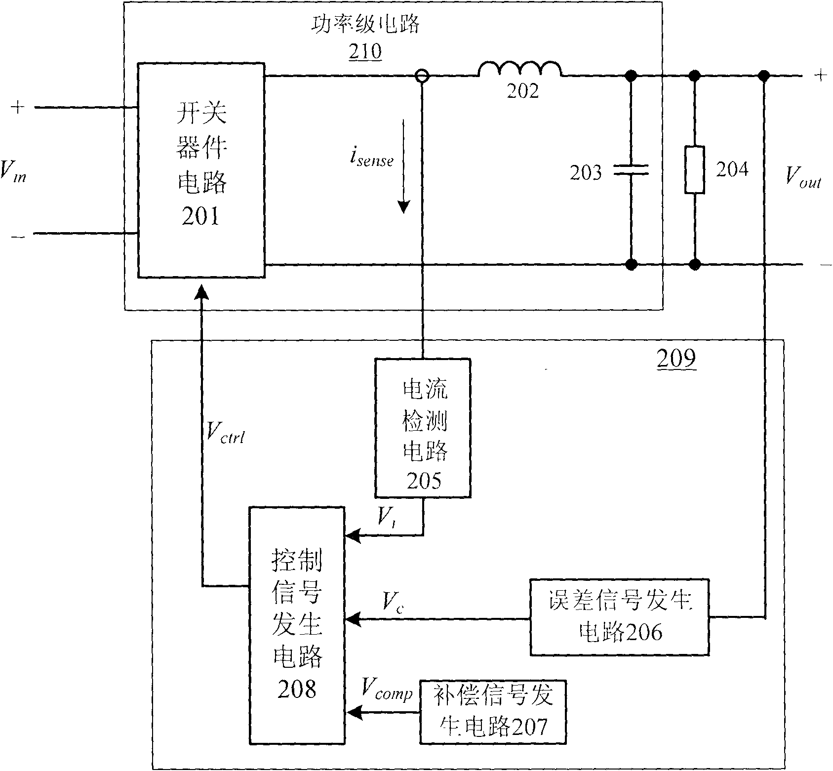
[0061] refer to Figure 2A , is shown as a circuit principle block diagram of the first embodiment of the current hysteresis control circuit according to the present invention. Wherein the switching device circuit 201, the inductor 202 and the capacitor 203 form a power stage circuit 210, which receives the input voltage V in . Current...


PUM


Abstract

The invention relates to a novel current hysteresis control circuit. According to the novel current hysteresis control circuit, an error signal generating circuit is used for receiving an output voltage and a reference voltage of a power-level circuit and generating an error signal; a current detection circuit is used for detecting the current in the power-level circuit so as to generate a detection voltage signal for representing current information in the power-level circuit; a compensation signal generating circuit is used for generating a slope compensation signal, the rise slope factor of which is a first slope factor, in the rise time interval of the detection voltage signal; a control signal generating circuit is used for receiving the error signal, the detection voltage signal andthe slope compensation signal; and the detection current information is compensated by an added slope compensation signal so as to effectively stabilize the working frequencies under different input voltage conditions and realize the transient response compensation to an output load, therefore transient response is improved.

Description

technical field [0001] The invention relates to a control circuit of a DC-DC converter, in particular to a current hysteresis loop control circuit adopting current mode control, a current hysteresis loop control method and a DC-DC converter applying the same. Background technique [0002] As the requirements for the steady-state and dynamic characteristics of the switching power supply are increasing day by day, higher requirements are also put forward for the control method in the switching power supply. Therefore, the double closed-loop control system with output voltage closed-loop control and current closed-loop control is widely used in switching power supplies because it meets the requirements of stability, control accuracy and dynamic characteristics at the same time. [0003] Among them, the current hysteresis control method is a relatively traditional PWM current control method, which has the advantages of good stability, fast response speed, and controllable error....

Claims


Application Information

Patent Timeline
IPC IPC(8): G05F1/56H02M3/156
Inventor 赵晨孙良伟
Owner SILERGY SEMICON TECH (HANGZHOU) CO LTD
Why Eureka
Try Eureka