
Method and device for splicing characteristic point correction partitions

A feature point correction and splicing device technology, applied in image analysis, image data processing, editing/combining graphics or text, etc., can solve problems such as information distortion

Active Publication Date: 2012-01-18
STATE GRID CORP OF CHINA +1
View PDF4 Cites 5 Cited by
  • Summary
  • Abstract
  • Description
  • Claims
  • Application Information

AI Technical Summary

Problems solved by technology

[0004] The main purpose of the present invention is to provide a feature point correction partition splicing method and device to solve the problem in the prior art that there is a risk of information distortion for positive vector scanning

Method used


Image

  • Method and device for splicing characteristic point correction partitions
  • Method and device for splicing characteristic point correction partitions
  • Method and device for splicing characteristic point correction partitions

Examples


Embodiment Construction

[0022] It should be noted that, in the case of no conflict, the embodiments in the present application and the features in the embodiments can be combined with each other. The present invention will be described in detail below with reference to the accompanying drawings and examples.

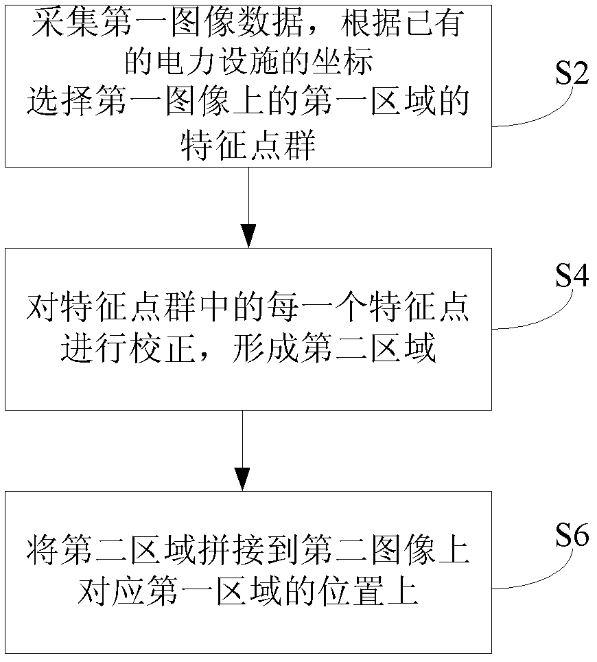
[0023] figure 1 It is a flow chart of main steps of the feature point correction partition stitching method according to the embodiment of the present invention.

[0024] see figure 1 As shown, the feature point correction partition stitching method of the present invention includes: S2: collect the first image data, and select the feature point group of the first area on the first image according to the coordinates of the existing power facilities; S4: select the feature point group Each feature point in the group is corrected to form a second area; and S6: stitching the second area to a position corresponding to the first area on the second image.

[0025] Through the technical solution of...


PUM


Abstract

The invention provides a method for splicing characteristic point correction partitions and is used for solving the problem of digital convergence of historical precious drawings in the prior art. The method comprises the following steps of: 2, acquiring first image data, and selecting a characteristic point group of a first area on a first image according to a preset coordinate; 4, correcting each characteristic point in the characteristic point group, and thus forming a second area; and 6, splicing the second area at a position, corresponding to the first area, on a second image. By adoption of the technical scheme of the invention, the problem of the digital convergence of various kinds of paper drawings which are accumulated over the years and include paper geologic maps with different time, different dryness and humidity and different scales can be effectively solved, the paper drawings can be accurately superposed and converged with geologic, geographic and grid vector data, and use requirements of stages such as scanning, designing, construction, running and maintenance on geologic information are met.

Description

technical field [0001] The invention relates to a feature point correction partition splicing method and device. Background technique [0002] With the urban construction, the geological conditions are becoming more and more complex, the cost of land acquisition and demolition is getting higher and higher, and the pressure of site selection for power projects is huge. However, the traditional board-type and decentralized geological data management mode has low work efficiency and low data utilization rate, and is increasingly unsuitable for the development of information technology. Scanning vectorization is to scan the geological information drawings, identify the lines and printed characters in the drawings, and convert them into vector lines and vector characters, so that they can be scaled with the electronic map. Due to the long-term preservation of historical precious drawings, due to folding and extrusion, the deformation of the drawings has been caused, and certain ...

Claims


Application Information

Patent Timeline
Patent Type & Authority Applications(China)
IPC IPC(8): G06T7/00G06T11/60
Inventor 舒彬王友军王勇
Owner STATE GRID CORP OF CHINA
Learn More