
Compensation device and method for display screen image in backlight local dimming system

A display screen and compensation device technology, applied to static indicators, instruments, etc., can solve problems such as insufficient brightness of bright backlight, loss of bright part detail clamping effect, and ripple effect on the screen

Active Publication Date: 2012-01-18
ORISE TECH CO LTD
View PDF5 Cites 16 Cited by
  • Summary
  • Abstract
  • Description
  • Claims
  • Application Information

AI Technical Summary

Problems solved by technology

[0006] Although the existing backlight area control methods can achieve the effect of improving image contrast and reducing power consumption, but often under inappropriate backlight determination and image compensation, the image quality is degraded instead, and color cast, image moire effect, and brightness loss often occur. Clamping effect of internal details, picture flickering, backlight not dark enough in dark frame and not bright enough in bright frame, etc.

Method used


Image

  • Compensation device and method for display screen image in backlight local dimming system
  • Compensation device and method for display screen image in backlight local dimming system
  • Compensation device and method for display screen image in backlight local dimming system

Examples


Embodiment Construction

[0030] In order to make the objectives, technical solutions and advantages of the present invention clearer, the present invention will be further described in detail below with reference to the accompanying drawings and specific embodiments.

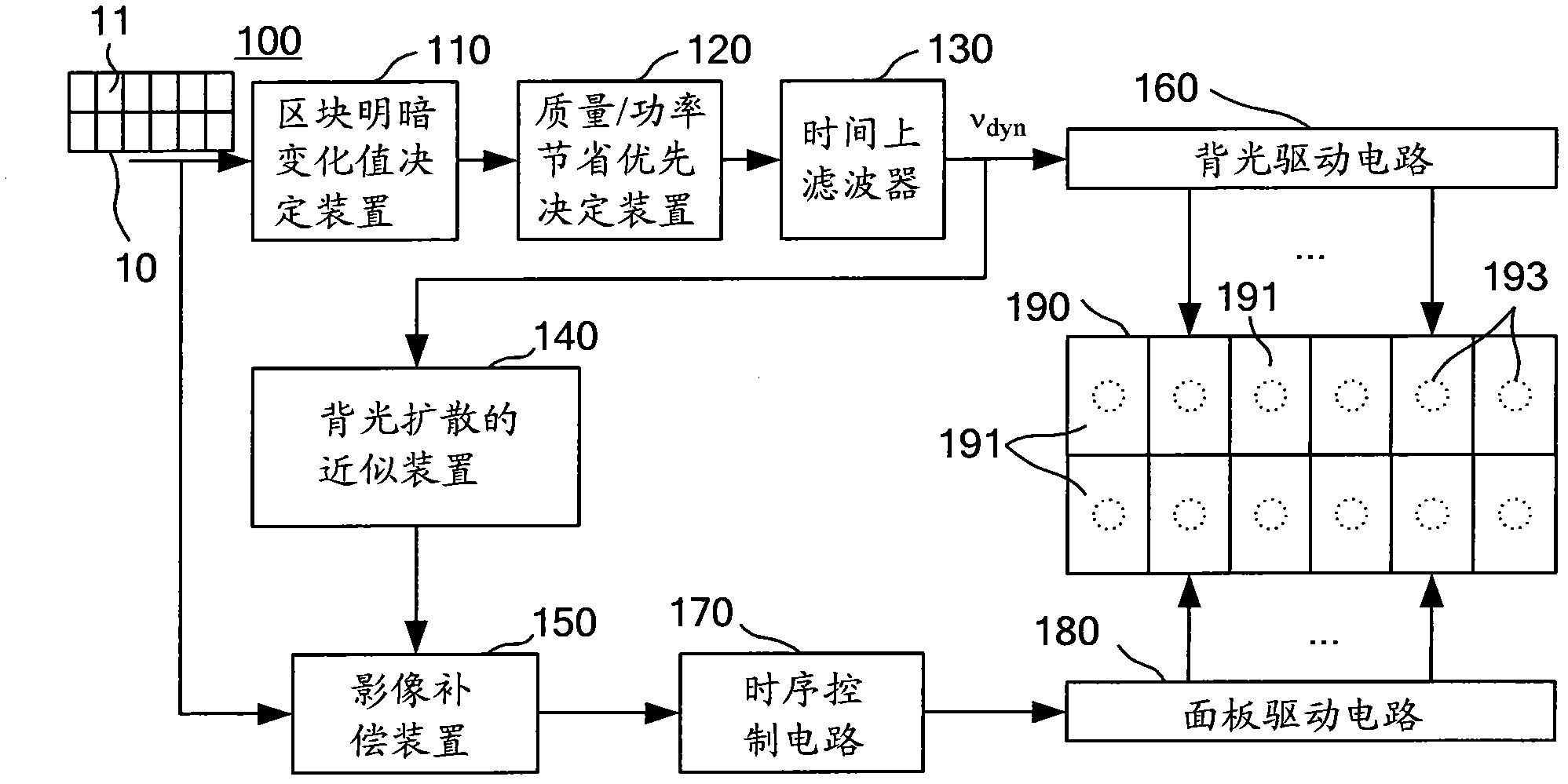
[0031] figure 1 It is a structural diagram of a compensation device 100 for displaying image images in a backlight area control system of the present invention, and the compensation device 100 is used in a liquid crystal display. The rear of the liquid crystal display panel 190 of the liquid crystal display is provided with a plurality of backlight sources 193, and the plurality of backlight sources 193 are arranged in a matrix form, wherein the display screen image 10 is divided into a corresponding number of image blocks 11 according to the plurality of backlight sources 193, also That is, the liquid crystal display panel 190 can be regarded as including a plurality of blocks 191 arranged in a matrix form, which are used to respective...


PUM


Abstract

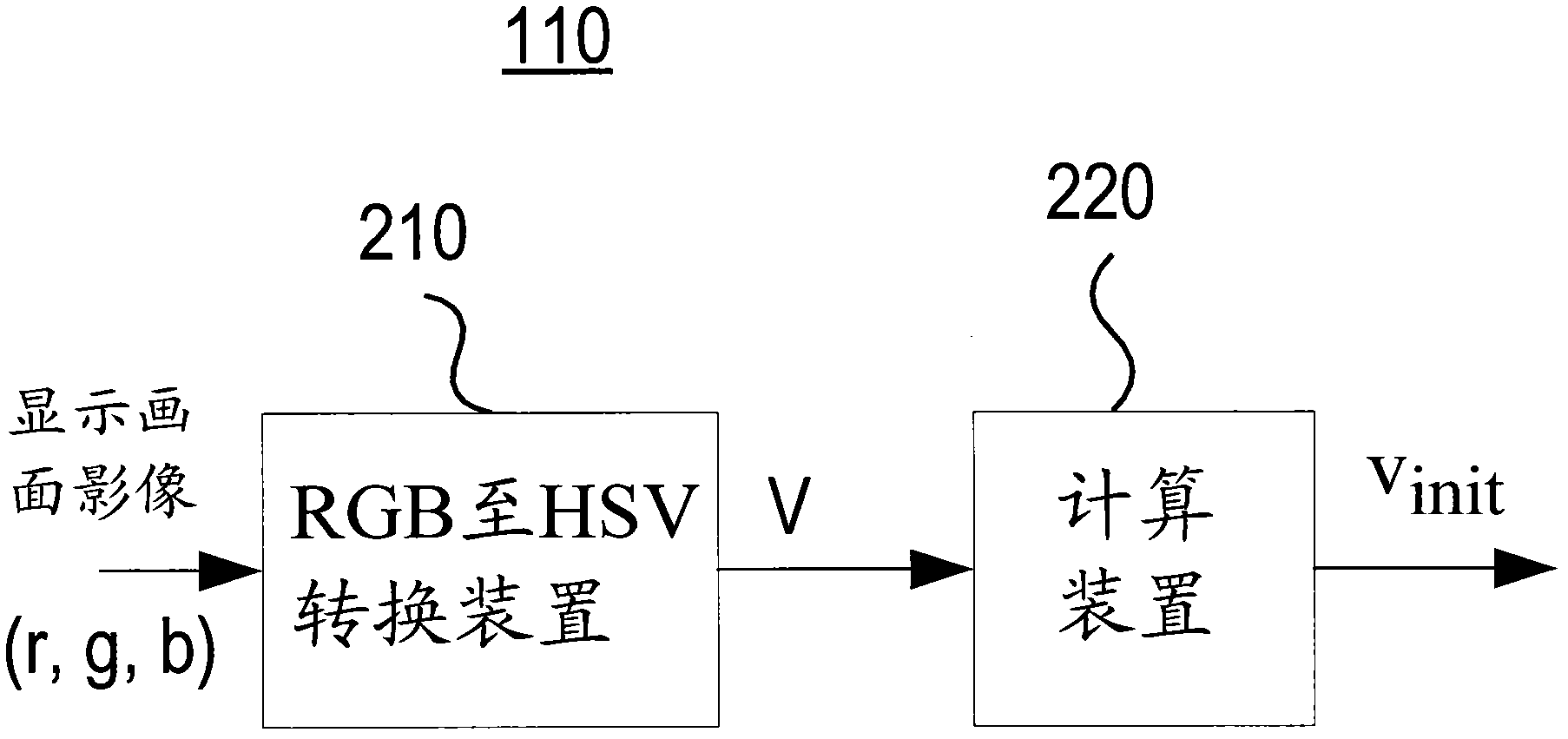
The invention discloses a compensation device and method for a display screen image in a backlight local dimming system. The display screen image is divided into a corresponding quantity of image blocks according to a plurality of backlights. A block brightness variation value deciding device receives the display screen image and calculates the average value, the maximum value and the initial value of the image blocks. A quality / power saving priority deciding device respectively generates backlight dimming signals to the image blocks according to the average value, the initial value, the first threshold value and the second threshold value of the image blocks. An on-time filter generates the backlight pulse width modulation signals of the image blocks according to the backlight dimming signal adaptabilities of the image blocks. A backlight-diffused approximating device generates a backlight-diffused image according to the backlight pulse width modulation signals of the image blocks. An image compensation device compensates the display screen image according to the backlight-diffused image to generate a compensated screen image. By adopting the device and the method disclosed by the invention, the calculation amount and the hardware circuit area can be reduced and the image quality can be improved.

Description

technical field [0001] The invention relates to the technical field of backlight area control, in particular to a compensation device and method for displaying image images in a backlight area control system. Background technique [0002] Existing LCD displays use multiple backlight sources, through which multiple display areas of the LCD display can be regulated, thereby achieving the purpose of power saving. Backlight local dimming means that the multiple backlight sources of the LCD display will be automatically adjusted according to the image brightness of the display screen, instead of being in a full-brightness state. [0003] In the existing LCD display, the backlight source is generally in a fully bright state. When displaying a dark state picture, it can be achieved by reducing the liquid crystal transmittance. Therefore, it does not help to reduce power consumption at all. In contrast, the backlight local dimming changes with the brightness of the screen. Therefor...

Claims


Application Information

Patent Timeline
Patent Type & Authority Applications(China)
IPC IPC(8): G09G3/36
Inventor 张智凯吴于立
Owner ORISE TECH CO LTD
Learn More