Preparation method of thermal battery electric pile assembly rack

A technology of thermal battery and assembly frame, which is applied to battery pack parts, circuits, electrical components, etc., can solve the problems of difficulty in entering the stack, reducing work efficiency, short-circuiting of fastening frames, etc., so as to reduce manufacturing costs and improve work efficiency. Efficiency and security effect

Inactive Publication Date: 2012-01-18
CHINA ELECTRONIC TECH GRP CORP NO 18 RES INST
View PDF2 Cites 5 Cited by
  • Summary
  • Abstract
  • Description
  • Claims
  • Application Information

AI Technical Summary

Problems solved by technology

[0003] With the continuous innovation, development and maturity of thermal batteries, there are more and more types of stack assembly. The traditional and simple assembly frame does not reserve a special space for the lead wires, and the position of the battery lead wires is not fixed, especially for multiple For a battery with multi-point fastening of the electric stack, on the radial circumference of the cylinder, the positive and negative taps of the electric stack are inevitably very close to a certain screw end of the assembly frame when the electric stack is assembled, so that the positive, negative The negative tap is easy to short-circuit with the fastening frame due to extrusion, and the positive and negative protective strips are also easy to overlap with the fastening strips in the fastening frame, making it difficult for the stack to enter the case, and it is very dangerous
At the same time, it is difficult to keep the battery stack relatively vertical during the assembly process, which requires special tooling and fixtures to operate when making batteries, which increases the difficulty of making hot batteries and reduces work efficiency.

Method used


Image

  • Preparation method of thermal battery electric pile assembly rack
  • Preparation method of thermal battery electric pile assembly rack
  • Preparation method of thermal battery electric pile assembly rack

Examples


Embodiment Construction

[0022] In order to further understand the invention content, characteristics and effects of the present invention, the following embodiments are enumerated hereby, and detailed descriptions are as follows in conjunction with the accompanying drawings:

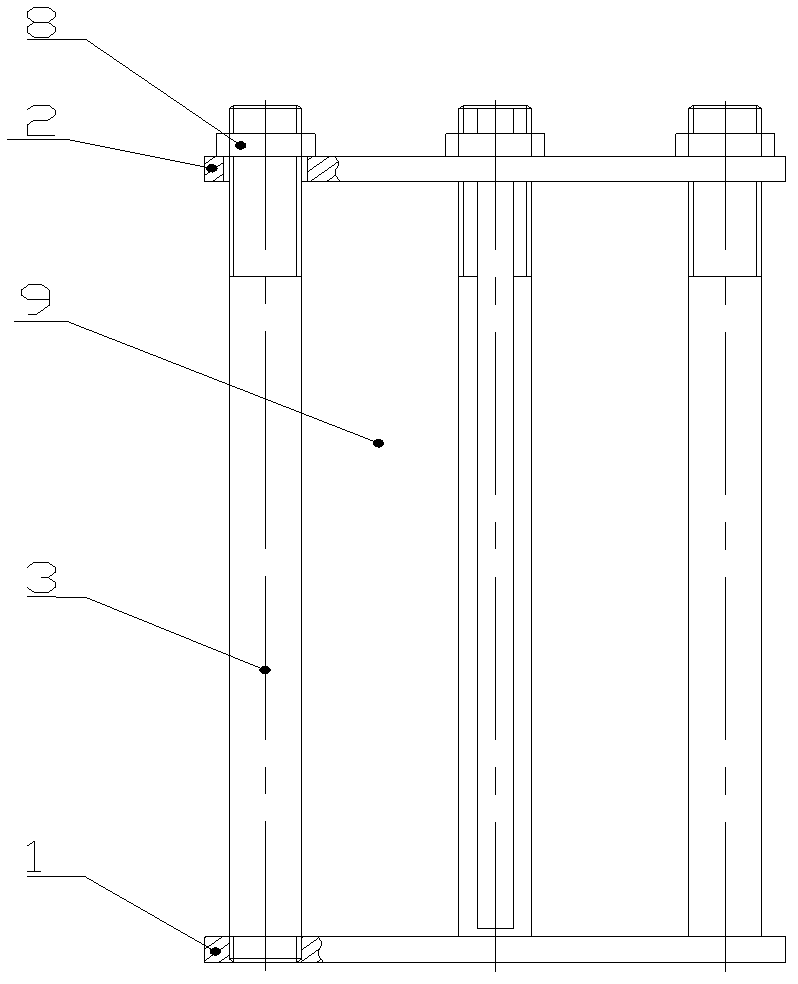
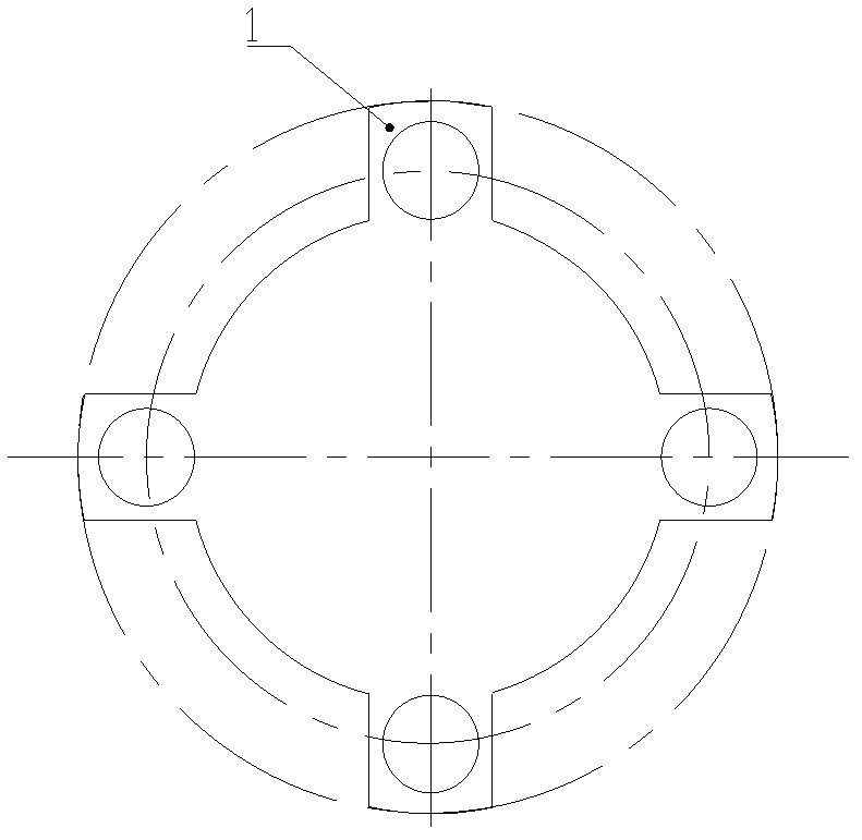
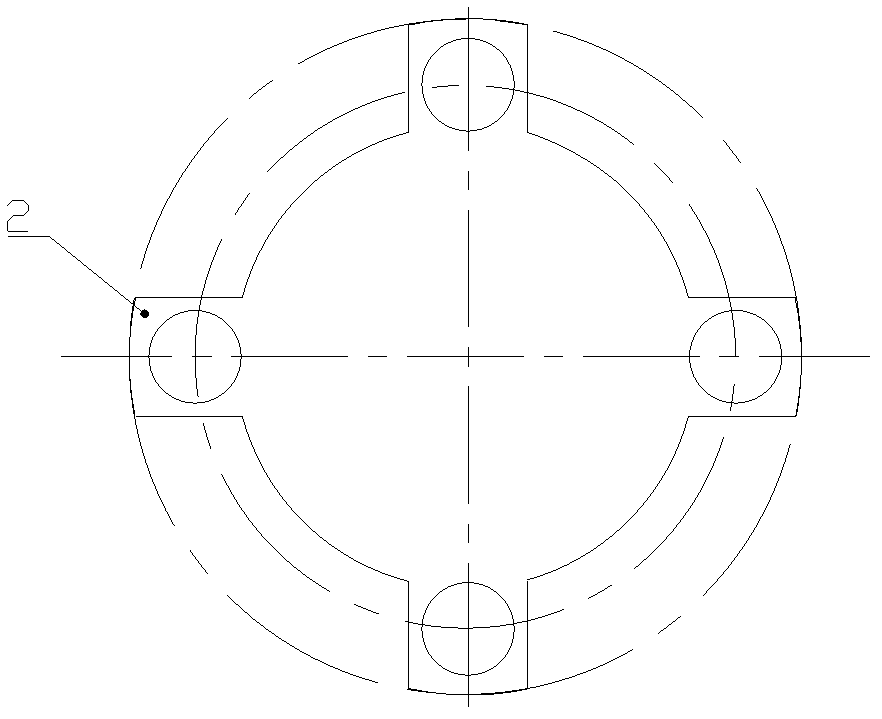
[0023] Refer to attached Figure 1-Figure 6 : A method for preparing a thermal battery stack assembly frame, comprising a lower platen 1, a stack 9, an upper platen 2 from bottom to top, and four screw rods 3 vertically connected between the upper platen and the lower platen.

[0024] The innovation of the present invention is: the screw body 4 of the screw is provided with a rectangular hole 5 in the radial direction, and the rectangular hole is a through hole or a blind hole; one end of the screw is an external thread 6, and there is a The semi-open groove 7 communicated with the rectangular hole, the screw rod is fixed on the upper pressing plate through the external thread and the nut 8; the screw rod and the lower pressing...


PUM


Abstract

The invention relates to a preparation method of a thermal battery electric pile assembly rack, and the preparation process comprises the following steps: (1) preparing a lower platen and an upper platen; (2) preparing screws, wherein one end of one of the screws has external threads, and a rectangular hole is located at the center part, and a half-open slot is provided on the external threads and is communicated with the rectangular hole; (3) assembling, that is, vertically fixing four screws on the lower platen, putting a single battery on the lower platen to form an electric pile, putting a lead wire in the rectangular hole, and leading out the lead wire from the half-open slot, covering the upper platen, pressing with a fastening nut so as to prepare a thermal battery electric pile assembly rack. The invention prepares the rectangular hole and the half-open slot communicated with the rectangular hole on the screw, provides the lead wire with accommodation space, and ensures the safety and original volume of the battery; four thread screws are used to ensure the verticality of the electric pile during assembling; the distance between the upper and the lower platens on the fastening rack can be adjusted conveniently according to the height of the electric pile; the working efficiency of battery preparation is increased; the manufacturing cost for the battery is reduced; and the requirements for batteries with different diameters and heights can be met.

Description

technical field [0001] The invention belongs to the technical field of thermal battery structure, and in particular relates to a preparation method of a thermal battery stack assembly frame. Background technique [0002] At present, the structural frame of the thermal battery stack includes an upper pressing plate, a lower pressing plate, and a fastening frame composed of fastening bars, which are used for stacking multiple single cells separated by insulating components. The structural frame has low resistance to the mechanical environment and is suitable for thermal batteries with a small stack height. [0003] With the continuous innovation, development and maturity of thermal batteries, there are more and more types of stack assembly. The traditional and simple assembly frame does not reserve a special space for the lead wires, and the position of the battery lead wires is not fixed, especially for multiple For a battery with multi-point fastening of the electric stack...

Claims


Application Information

Patent Timeline
Patent Type & Authority Applications(China)
IPC IPC(8): H01M2/10
CPCY02E60/12Y02E60/10
Inventor 李彦南张卫红赵莉焱武艳波石奎
Owner CHINA ELECTRONIC TECH GRP CORP NO 18 RES INST
Why Eureka
Try Eureka