Miniaturization substrate integrated multi-beam antenna

A multi-beam antenna and substrate integration technology, applied in the direction of antenna, antenna array, radiating element structure, etc., can solve the problems of complex design and large volume, achieve compact structure, high radiation efficiency, reduce area and complex structure degree of effect

Active Publication Date: 2012-01-18
CHENGDU RDW TECH CO LTD
View PDF4 Cites 38 Cited by
  • Summary
  • Abstract
  • Description
  • Claims
  • Application Information

AI Technical Summary

Problems solved by technology

Since the above three modules need to be cascaded in sequence and a

Method used


Image

  • Miniaturization substrate integrated multi-beam antenna
  • Miniaturization substrate integrated multi-beam antenna
  • Miniaturization substrate integrated multi-beam antenna

Examples


Embodiment Construction

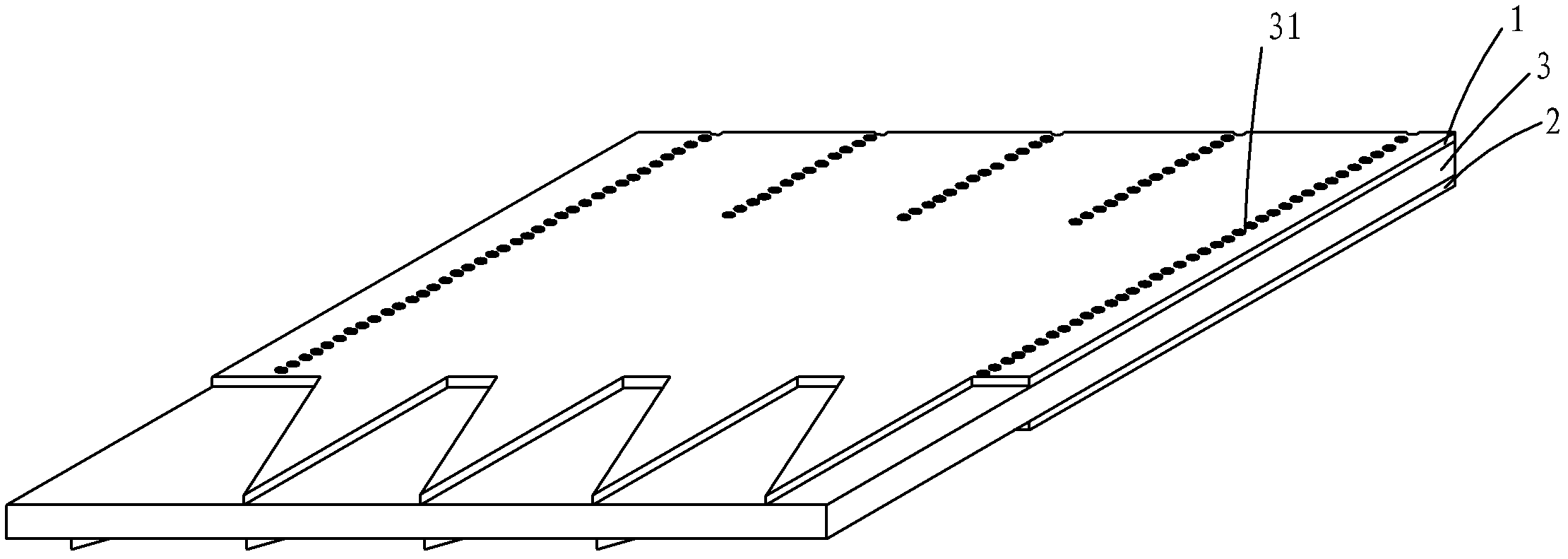
[0015] Such as figure 2 , image 3 , Figure 4 , Figure 5 , Figure 6 As shown, a miniaturized substrate-integrated multi-beam antenna includes a metal copper-clad upper layer 1, a dielectric layer 3, and a metal-clad copper lower layer 2 stacked sequentially from top to bottom. In order to form the miniaturized substrate integrated multi-beam antenna of the present invention For the antenna, the metal copper-clad upper layer 1 and the metal copper-clad lower layer 2 are processed through the printed circuit board manufacturing process to form the required metal pattern (circuit structure), and the various parts of the pattern are divided by virtual dotted lines, The medium layer 3 is drilled and the surface of the hole is metallized to form a metallized through hole 31, and the metal-clad copper upper layer 1 includes a direction from the input end to the radiation end ( Figure 5 The feeding table area 11 arranged in sequence from right to left in the middle, the multi...


PUM


Abstract

The invention relates to a miniaturization substrate integrated multi-beam antenna which comprises a metal copper-clad upper layer, a dielectric layer and a metal copper-clad lower layer which are sequentially laminated from top to bottom, wherein the metal-clad upper layer comprises a feed upper meter area, a multi-mode upper meter area and N groups of triangular upper meter areas which are sequentially arrayed from the input end to the radiation end; the multi-mode upper meter area is connected with the feed upper meter area; the N groups of triangular upper meter areas are connected with the multi-mode upper meter area; the metal copper-clad lower layer comprises a feed lower meter area, a multi-mode lower meter area and N groups of triangular lower meter areas; the feed lower meter area, the multi-mode lower meter area and the N groups of triangular lower meter areas are sequentially arrayed from the input end to the radiation end; the multi-mode lower meter area is connected with the feed lower meter area; the N groups of triangular lower meter areas are connected with the multi-mode lower meter area; and the dielectric layer is internally provided with N+1 rows of metallized through holes which penetrate through the feed upper meter area and the dielectric layer and are connected with the feed lower meter area as well as penetrate through the feed upper meter area and the dielectric layer and are connected with the multi-mode lower meter area. The invention has the benefit that a multi-beam antenna structure is compact, thus higher radiation efficiency is acquired.

Description

technical field [0001] The invention belongs to the technical field of microwave and millimeter wave antennas, in particular to a substrate-integrated waveguide multi-beam antenna. Background technique [0002] As a kind of smart antenna, the multi-beam antenna can generate multiple beams with different directions, and can select the beam to align with the useful signal direction, thereby reducing interference and increasing the channel capacity of the system, so it has been widely used in the field of high-speed wireless communication. focus on. [0003] So far, researchers have realized several different types of multi-beam antennas based on various waveguide structures such as microstrip lines, metal waveguides, and substrate-integrated waveguides. Among them, the multi-beam antenna composed of substrate-integrated waveguides has the advantages of low metal loss, low radiation mutual coupling, easy integrated design, low processing cost, good repeatability, and easy mass...

Claims


Application Information

Patent Timeline
IPC IPC(8): H01Q21/00H01Q3/26H01Q1/38
Inventor 程钰间樊勇
Owner CHENGDU RDW TECH CO LTD
Why Eureka
Try Eureka