
Electro-pneumatic pressure regulation module comprising pressure regulation channels having separate pneumatic circuits

A technology of pressure regulation and pneumatic circuit, which is applied in the direction of brake transmission, brakes, brake components, etc., and can solve problems such as pressure channel failure

Inactive Publication Date: 2012-01-18
KNORR BREMSE SYST FUER NUTZFAHRZEUGE GMBH
View PDF8 Cites 15 Cited by
  • Summary
  • Abstract
  • Description
  • Claims
  • Application Information

AI Technical Summary

Problems solved by technology

The disadvantage of this design is that if this compressed air reserve fails or if there is a rupture in the reserve air duct feeding the two-channel pressure regulation module, both pressure channels will fail

Method used


Image

  • Electro-pneumatic pressure regulation module comprising pressure regulation channels having separate pneumatic circuits
  • Electro-pneumatic pressure regulation module comprising pressure regulation channels having separate pneumatic circuits
  • Electro-pneumatic pressure regulation module comprising pressure regulation channels having separate pneumatic circuits

Examples


Embodiment Construction

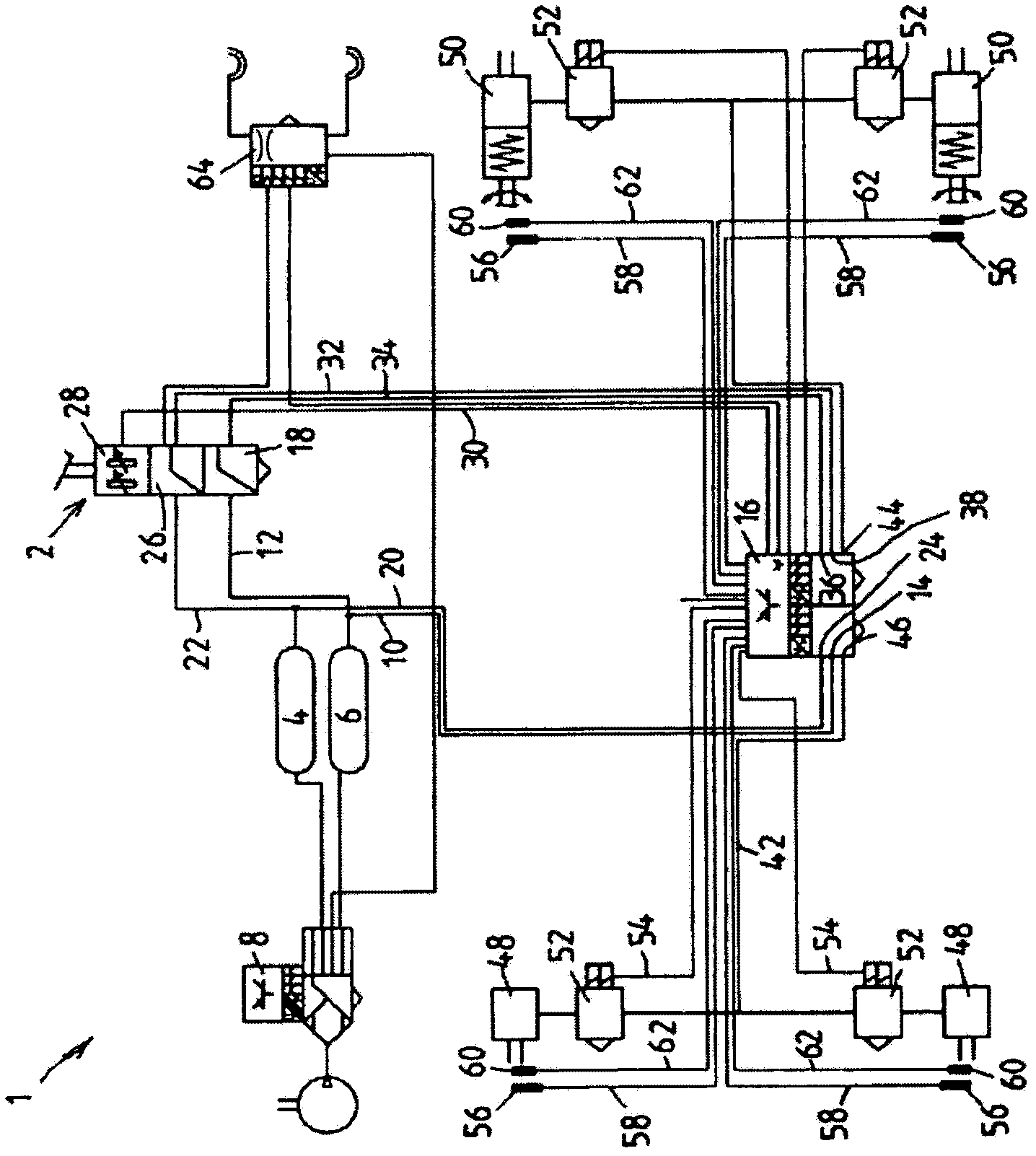
[0039] figure 1 A circuit diagram of an electropneumatic service brake system 1 for a commercial vehicle is shown, which has: a foot brake parameter sensor 2; a front axle reserve pressure vessel 4 for supplying the front axle pressure circuit or front axle pressure channel; Axle reserve pressure vessel 6 for supplying the rear axle pressure circuit or rear axle pressure channel.

[0040] Air supply, air conditioning and security are implemented as required by law via an air conditioning module 8 which is not described in detail here.

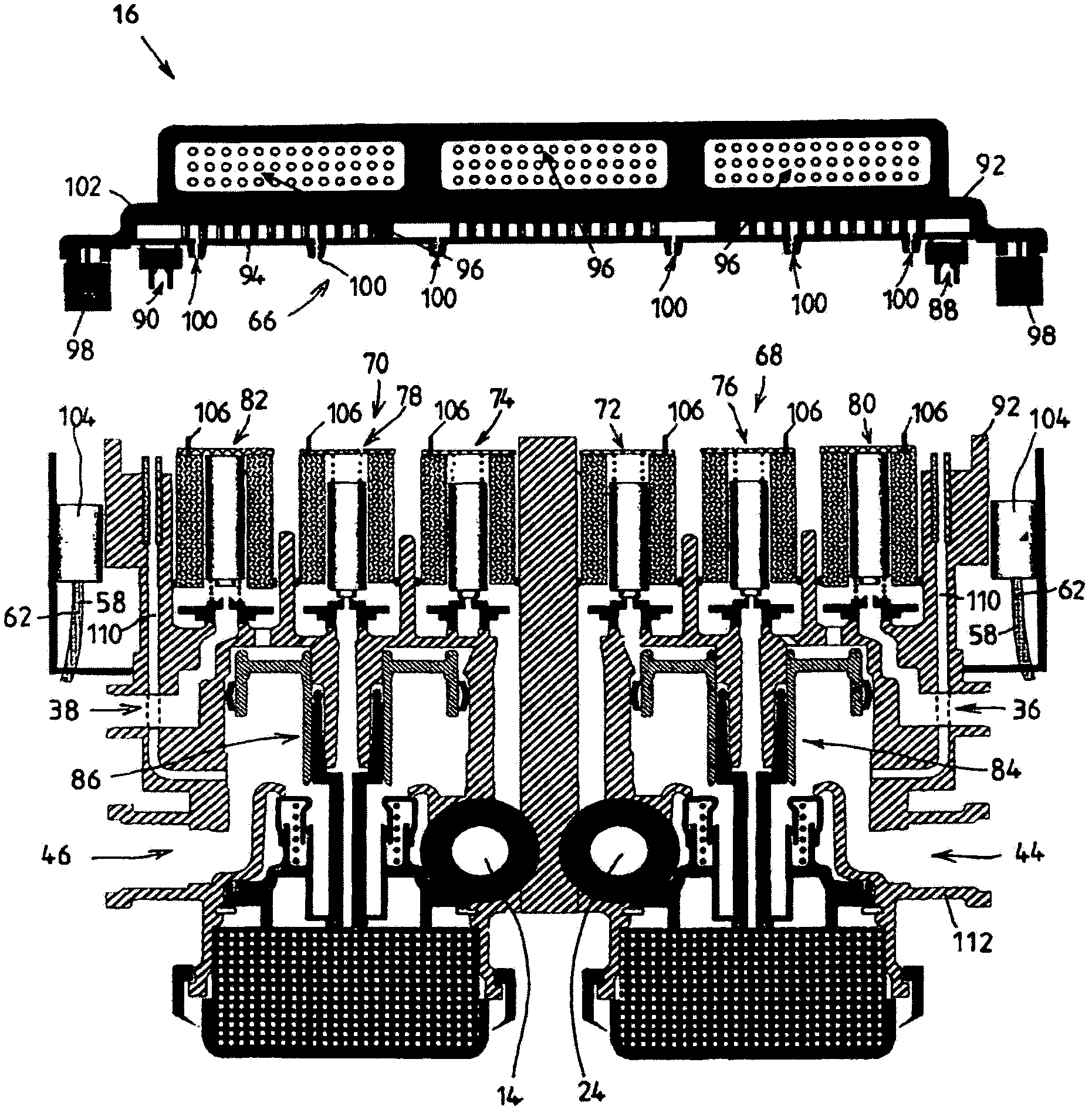
[0041] The rear axle reserve pressure container 6 is connected to the rear axle reserve interface 14 of the dual channel pressure regulating module 16 and connected to the front axle foot brake valve 18 of the foot brake parameter sensor 2 through the pneumatic supply pipelines 10 and 12 .

[0042] In a similar manner, the front axle reserve pressure container 4 is connected to the front axle reserve interface 24 of the dual-channel pressure r...


PUM


Abstract

The invention relates to an electro-pneumatic pressure regulation module (16) for electro-pneumatic brake systems of vehicles, designed as a unit, comprising at least two pressure regulation channels which can be regulated separately, wherein for each pressure regulation channel a regulated working pressure, which is present on at least one working pressure port (44, 46), is generated for at least one brake application device (48, 50) of the brake system based on working air that is derived from at least one compressed air supply (4, 6), depending on the brake demand signals of a braking power sensor (2). The invention includes a) that in order to create pressure regulation channels having separate pneumatic circuits, at least one dedicated supply pressure port (14, 24), which can be connected to a dedicated compressed air supply (4, 6), is assigned to each pressure regulation channel, wherein b) the pneumatic flow paths of each pressure regulation channel, at least starting from the respective supply pressure port (14, 24) to the respective working pressure port (44, 46), are designed pneumatically separate from the pneumatic flow paths of the respectively other pressure regulation channel.

Description

technical field [0001] The invention relates to an electropneumatic pressure regulation module designed as a combined unit for an electropneumatic brake system of a vehicle according to the preamble of claim 1 , having at least two separable Regulated pressure regulation channels, wherein, for each pressure regulation channel, on the basis of working air from at least one compressed air reserve, as a function of the brake request signal from the brake parameter sensor, at least one brake pressure of the brake system The tightening device generates a regulated working pressure which is present at at least one working pressure connection. Background technique [0002] A suitable pressure regulation module is known from EP 1 122 142 A1. A known pressure control module is a two-channel pressure control module as a rear axle module, wherein each channel supplies a wheel brake of the rear axle with brake pressure or operating pressure. In contrast, the wheel brake cylinders of t...

Claims


Application Information

Patent Timeline
Patent Type & Authority Applications(China)
IPC IPC(8): B60T8/32B60T8/34B60T13/68
CPCB60T8/3675B60T8/327B60T13/683B60T8/343
Inventor 于尔根·施泰因贝格尔彼得·弗兰克迈克尔·赫格斯马丁·梅德尔
Owner KNORR BREMSE SYST FUER NUTZFAHRZEUGE GMBH
Learn More