
Main spindle box for milling and drilling machine

A spindle box, milling and drilling technology, applied to other manufacturing equipment/tools, metal processing machinery parts, maintenance and safety accessories, etc., can solve the problem that machine tool equipment cannot meet the processing requirements of complex parts, reduce temperature and ensure processing Accuracy, ingenious structure and reasonable effect

Inactive Publication Date: 2012-01-25
无锡桥联数控机床有限公司
View PDF7 Cites 16 Cited by
  • Summary
  • Abstract
  • Description
  • Claims
  • Application Information

AI Technical Summary

Problems solved by technology

[0002] With the development of large-scale equipment manufacturing industry, the performance requirements of large-scale CNC machine tools are getting higher and higher in the market. Machine tool equipment with only a single processing and production function can no longer meet the processing needs of complex parts, and it is replaced by compound processing machine tools.

Method used


Image

  • Main spindle box for milling and drilling machine
  • Main spindle box for milling and drilling machine
  • Main spindle box for milling and drilling machine

Examples


Embodiment Construction

[0018] The present invention will be further described below in conjunction with specific drawings and embodiments.

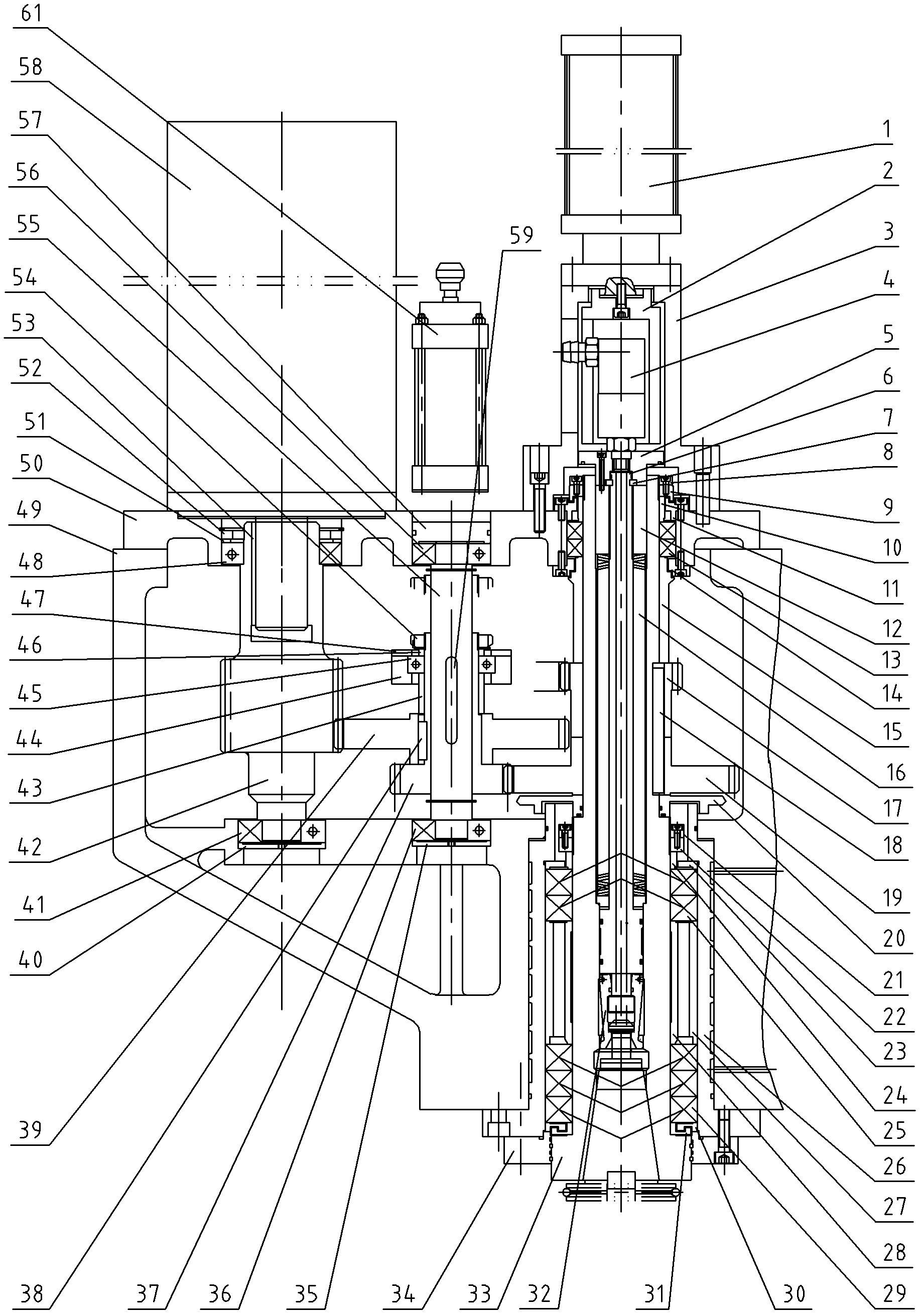
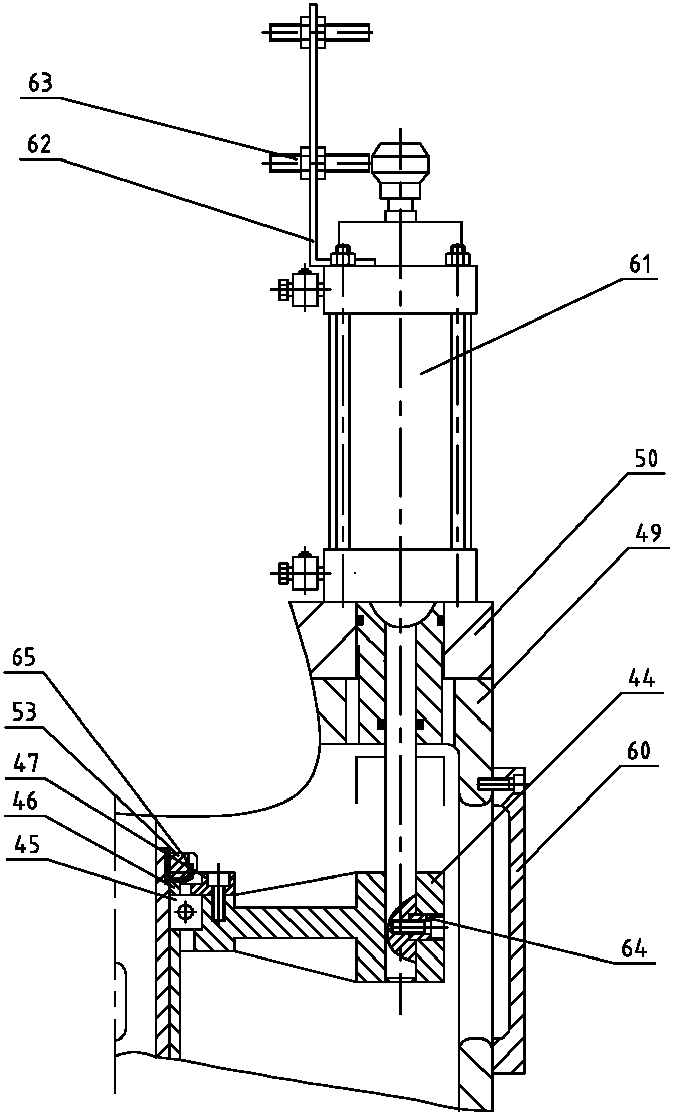
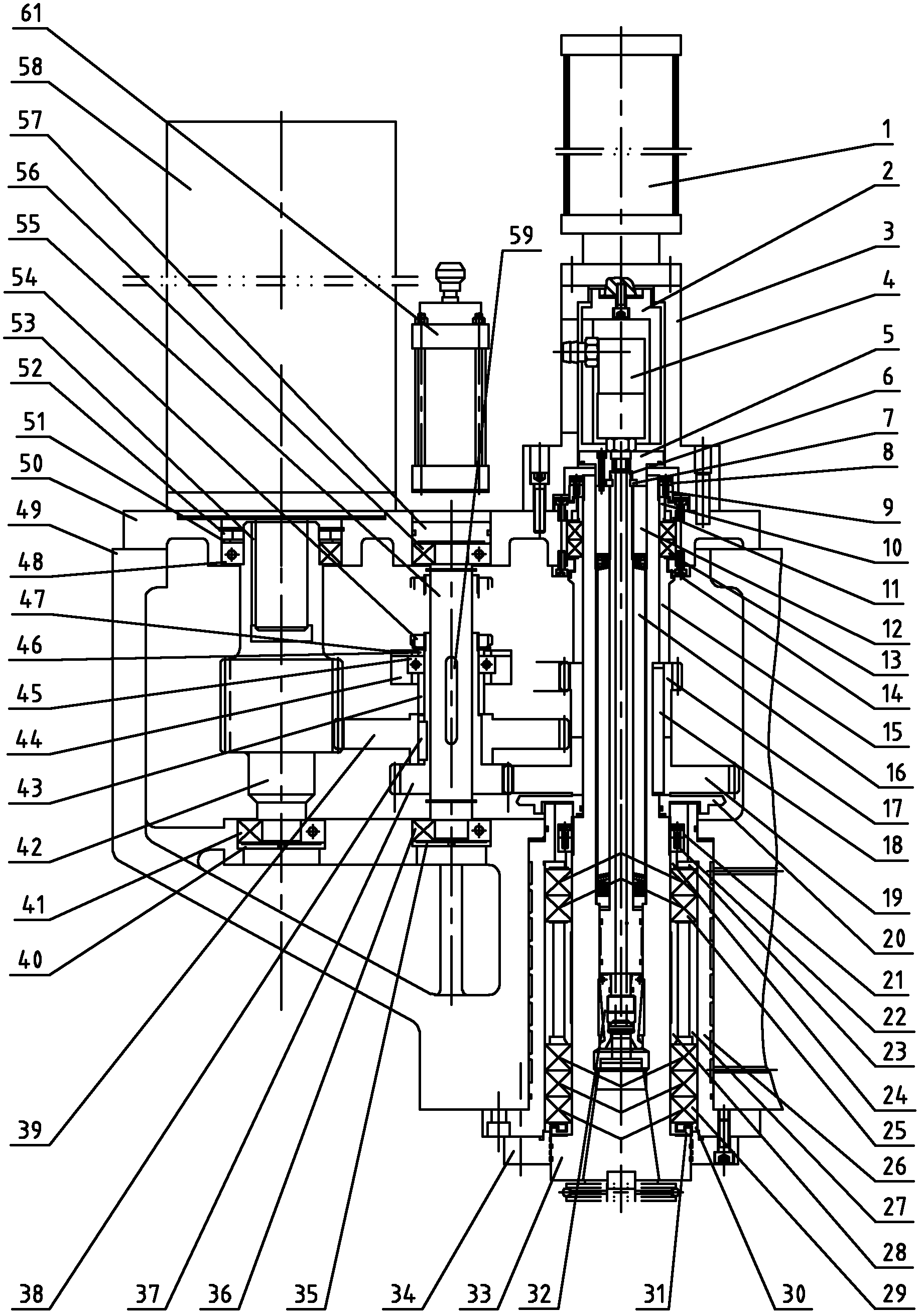
[0019] As shown in the figure: the present invention mainly consists of a booster cylinder 1, a pressure sleeve 2, a booster cylinder seat 3, a rotary joint 4, a cover 5, a pull rod 6, a spacer 7, a rear outer nut 8, a rear inner nut 9, and a spacer 10. Sealing cover 11, pull rod nut 12, support bearing group 13, bearing cover 14, spacer 15, butterfly spring group 16, small output gear 17, flat key 18, large output gear 19, spacer 20, front outer nut 21. Front inner nut 22, spacer 23, spacer 24, first bearing group 25, water jacket 26, outer spacer 27, inner spacer 28, second bearing group 29, outer spacer 30, inner spacer 31 , Claw 32, Main shaft 33, Flange cover 34, Take out pad 35, Lower bearing 36, Small transmission gear 37, Flat key 38, Large transmission gear 39, Take out pad 40, Lower bearing 41, Gear shaft 42, Spacer ring 43 , fork 44, bearing 45, pad...


PUM


Abstract

The invention relates to a main transmission box for a milling and drilling machine. The main transmission box comprises a sealed cavity composed of a box body and a box cover, and an input shaft component, a transmission shaft component and an output shaft component are mounted in the sealed cavity. The main transmission box is characterized in that a gear shaft is rotatably mounted in the sealed cavity, a main shaft motor is mounted on the sealed cavity, an output shaft of the main shaft motor is connected with the gear shaft; the transmission shaft can be rotatably mounted in the sealed cavity, and a high-low-drive gear set is assembled on the transmission shaft in a sliding manner; a large transmission gear in the high-low-drive gear set is always engaged with a gear shaft in the input shaft component; the main shaft can be rotatably mounted in the sealed cavity, a large output gear and a small output gear are mounted on the main shaft; a main shaft broaching-loosening cutter is arranged in the main shaft for firmly grasping a cutter. The transmission shaft box has rational and clever structure, and can meet a high output torque demand of the main shaft milling processing and a high output rotation speed demand of the drilling processing, can effectively meet the milling-drilling composite processing demands of parts. By the adoption of the transmission shaft box, the working efficiency can be obviously improved and the processing precision can be ensured.

Description

Technical field [0001] The present invention involves a special proportion of the milling diamond machine used in the CNC milling and drilling machine, which is a mechanical structure technology field. Background technique [0002] With the development of large -scale equipment manufacturing industries, the performance requirements of large CNC machine tools in the market are getting higher and higher. Machine tool equipment with single processing production functions is increasingly unable to meet the processing needs of complex components.EssenceThe composite machining machine tool is two or more processing functions on one processing equipment. The production process that needs to be completed by two or more processing machine tools before completing one processing equipment can be greatly improved.efficiency. [0003] The milling processing of the machine tool mainly relies on the output torque of the main axis, and the speed requirements of the main axis during drilling proc...

Claims


Application Information

Patent Timeline
Patent Type & Authority Applications(China)
IPC IPC(8): B23B19/00B23B19/02B23Q11/12B23P23/02
Inventor 叶穗强海华黄俊桂徐彬周晖
Owner 无锡桥联数控机床有限公司
Learn More