Electromagnetic valve

A solenoid valve and valve seat technology, applied in the field of solenoid valves, can solve the problems of high processing cost, high energy consumption, and high energy consumption of solenoid valves for balance holes, so as to achieve energy saving effects, reduce cross-sectional area, and improve valve opening effect of ability

Active Publication Date: 2012-01-25
浙江中宝自控元件有限公司
5 Cites 21 Cited by

AI-Extracted Technical Summary

Problems solved by technology

The larger the cross-sectional area of ​​the axial through hole at the center of the piston, the greater the power of the coil that drives the moving iron core to move upward, and the greater the energy consumption. Due to the existence of the balance ...

Abstract

The invention discloses an electromagnetic valve belonging to the field of valves and comprising a main valve and a pilot valve, wherein the main valve comprises a valve seat, and a piston accommodated in an inner cavity of the valve seat; the valve seat is provided with an input hole, an output hole and a pilot valve installing hole which are communicated with the inner cavity; the lower end part of the piston is sealed and covered on the output hole, the upper end part of the piston is provided with a groove, the bottom of the groove is provided with a piston valve hole communicated with the output hole; the pilot valve comprises a spring, a coil, a guide sleeve arranged on the pilot valve installing hole, a static iron core and a movable iron core, wherein the static iron core and the movable iron core are respectively arranged at the upper end and the lower end of an inner cavity of the guide sleeve, the coil is sleeved on the outer surface of the guide sleeve, the lower port of the guide sleeve is provided with a limit baffle ring, the lower end part of the movable iron core penetrates through a valve hole of a sealing piston of the limit baffle ring, the movable iron core is provided with an axial step through hole and a transverse hole which are penetrated, and the spring is arranged at the upper section of the step through hole and abuts and supports against the static iron core. The electromagnetic valve is characterized in that a transverse groove is arranged on the lower end face of the limit baffle ring, thus medium channel area between the input hole and the groove is reduced, valve-opening capacity is improved and energy-saving effect is realized.

Application Domain

Technology Topic

Image

  • Electromagnetic valve
  • Electromagnetic valve
  • Electromagnetic valve

Examples

  • Experimental program(1)

Example Embodiment

[0013] The specific embodiments of the present invention will be described in detail below with reference to the accompanying drawings.
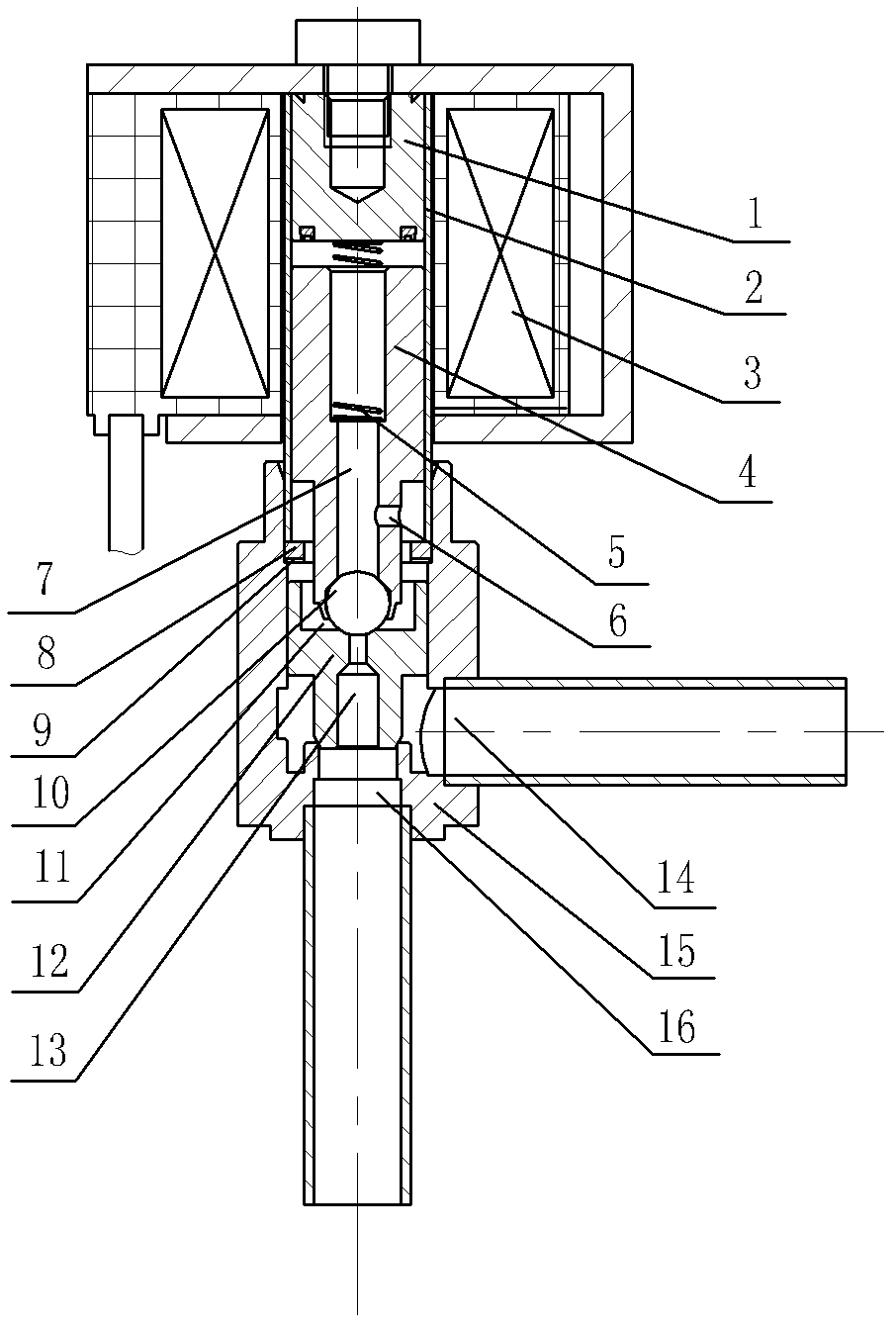
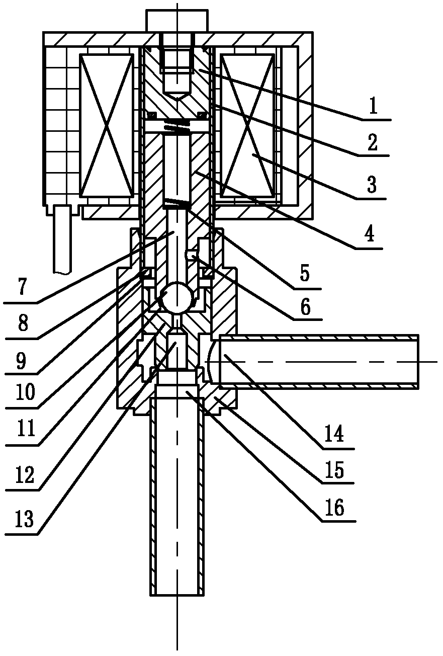
[0014] Such as figure 1 , figure 2 As shown, the present invention includes a main valve and a pilot valve. The main valve includes a valve seat 15 with an inner cavity and a piston 12. The piston 12 is accommodated in the inner cavity of the valve seat 15 and can move axially, and the valve seat 15 is provided There are input holes 14, output holes 16 and pilot valve mounting holes that all communicate with the inner cavity. The pilot valve mounting hole is located at the upper end of the inner cavity of the valve seat, and its center line is in the same direction as the piston movement direction. The orifice of the output hole 16 is located in the valve The bottom surface of the inner cavity of the seat is directly opposite to the end surface of the piston; the piston 12 includes an upper end and a lower end. The diameter of the lower end is smaller than that of the upper end. The lower end is closed on the opening of the output hole 16, and the upper end is provided with a groove 11, concave The bottom of the groove is provided with a piston valve hole 13 communicating with the valve seat output hole 16; the pilot valve includes a guide sleeve 2, a static iron core 1, a movable iron core 4, a spring 5 and a coil 3. The guide sleeve 2 is installed on the pilot Valve mounting hole, the coil 3 is sleeved on the outer surface of the guide sleeve 2. The lower port of the guide sleeve 2 is provided with a limit stop ring 8. The center of the limit stop ring 8 is a through hole, and the static iron core 1 is fixedly installed on the guide sleeve 2. At the upper end of the inner cavity, the movable iron core 4 is accommodated at the lower end of the inner cavity of the guide sleeve 2. The diameter of the lower end of the movable iron core 4 is smaller than the diameter of the main body of the movable iron core 4, and the lower end of the movable iron core 4 has a containing cavity. A steel ball valve core 10 is clamped in the cavity. The lower end of the movable iron core passes through the central through hole of the stop ring 8. The valve core 10 and the piston valve hole 13 are matched and sealed. The movable iron core 4 is provided with an axial stepped through hole. 7. The lower end of the moving iron core is provided with a transverse hole 6 penetrating the stepped through hole 7, so that high-pressure medium can be input into the inner cavity of the guide sleeve between the moving iron core and the static iron core. The upper section of the stepped through hole 7 has a larger diameter than the lower section. The spring 5 is arranged in the upper section of the stepped through hole and is in contact with the static iron core 1; the lower end surface of the limit stop ring 8 is provided with a transverse groove 9, and the upper end surface of the piston and the lower end surface of the limit single ring can be formed from the outer side of the piston To the medium channel of the groove on the upper end surface of the piston, the high-pressure medium enters the groove through the transverse groove.
[0015] As another embodiment, the upper end surface of the piston 12 can also be provided with a transverse groove, which is an equivalent means and should be regarded as the protection scope of this patent. The upper end surface of the piston can be formed when the upper end surface of the piston is attached to the lower end surface of the limit single ring. The medium passage from the outer side of the piston to the groove on the upper end of the piston.
[0016] When the solenoid valve is in use, the input hole is connected to the input pipe to input high pressure medium, and the output hole is connected to the output pipe. When the solenoid valve is closed, the lower end of the piston is sealed with the output hole of the valve seat, and the valve core cover at the lower end of the moving iron core is sealed At the orifice of the piston valve, the high-pressure medium enters the groove through the gap between the piston and the valve seat, so that the pressure on both ends of the piston is balanced. When the solenoid valve needs to be opened, the coil drives the moving iron core to move up to make the lower end of the The valve core is separated from the piston valve port, and the high-pressure medium in the groove is discharged into the output pipe through the piston valve hole of the piston. When the cross-sectional area of ​​the piston valve hole is larger than the clearance area between the piston and the valve seat, the pressure in the groove will change When lowering, the piston moves up and disengages. When the solenoid valve needs to be closed, the moving iron core moves down. The valve core cover at the lower end of the moving iron core is sealed to the piston valve port and generates downward pressure on the piston. The high pressure medium passes between the piston and the valve seat The gap and the transverse groove enter the groove on the piston to accelerate the downward movement of the piston.

PUM

no PUM

Description & Claims & Application Information

We can also present the details of the Description, Claims and Application information to help users get a comprehensive understanding of the technical details of the patent, such as background art, summary of invention, brief description of drawings, description of embodiments, and other original content. On the other hand, users can also determine the specific scope of protection of the technology through the list of claims; as well as understand the changes in the life cycle of the technology with the presentation of the patent timeline. Login to view more.

Similar technology patents

Classification and recommendation of technical efficacy words

Why Eureka
Try Eureka