
LED lamp

A technology of LED lamps and LED lamp boards, which is applied in the field of lamps and lanterns, can solve the problems of affecting the service life of the whole lamp, the loose connection between the lamp head and the heat sink, and LED short circuit, so as to improve the stability of use, solve the short circuit phenomenon, and prolong the service life Effect

Inactive Publication Date: 2012-01-25
NINGBO FUTAI ELECTRIC CO LTD
View PDF5 Cites 20 Cited by
  • Summary
  • Abstract
  • Description
  • Claims
  • Application Information

AI Technical Summary

Problems solved by technology

[0004] In order to facilitate the fixed connection of the lamp cap and the heat sink of the LED lamp, a base is used to fix the lamp cap and the heat sink in the structure of the LED lamps on the market now, but the above-mentioned structure is convenient for the installation of the lamp cap and the heat sink. It is not a direct connection. After a period of use, the connection between the lamp head and the radiator will become loose, which will affect the service life of the whole lamp. This is a technical defect in the production of LED lamps at this stage; there are also widely used LED lamps and lanterns, the LED substrate and heat sink are often directly fixed by metal screws, because metal is easy to conduct electricity and heat conduction, and the metal screws are too close to the LED light source during installation, which will cause short-circuit phenomenon in the LED during use.

Method used


Image

  • LED lamp
  • LED lamp
  • LED lamp

Examples


Embodiment 1

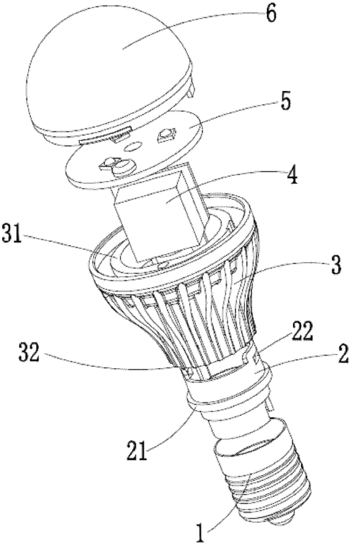
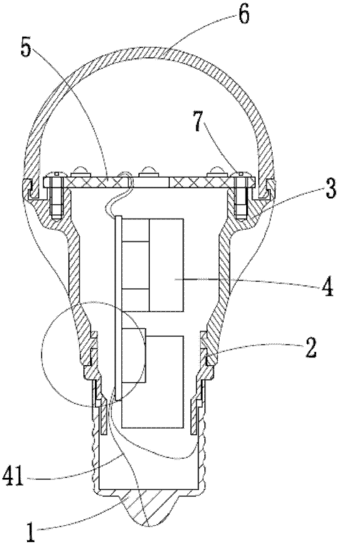
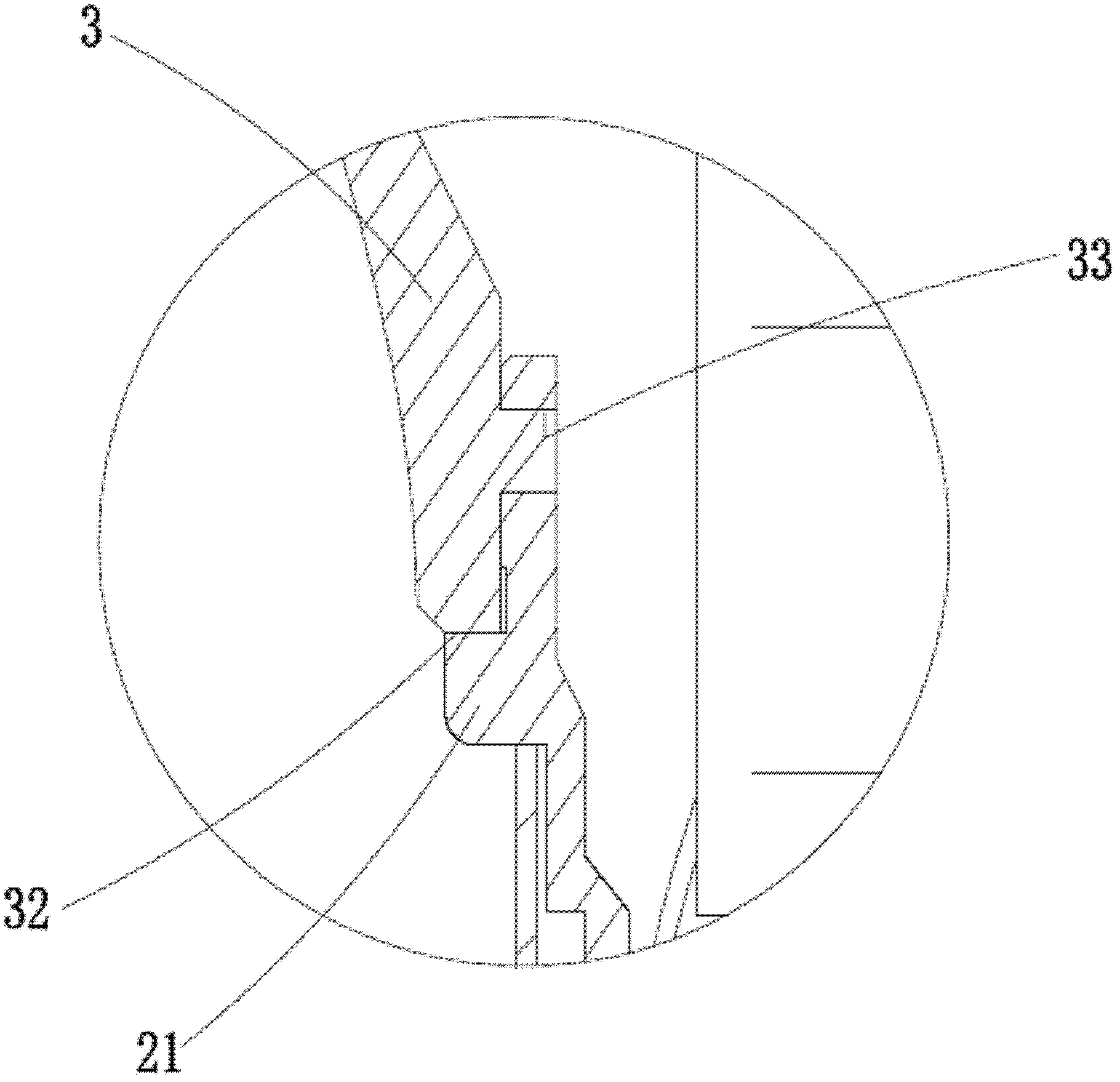
[0016] Such as figure 1 , figure 2 , image 3 As shown, the LED lamp provided in this embodiment includes a lamp cap 1, a radiator 3, an electronic component 4, an LED lamp board 5 and a lampshade 6, the lamp cap 1 is connected to the radiator 3 through a base 2, and the electronic component 4 is placed between the lamp cap 1 and the lampshade 6. In the inner cavity formed by the connection of the heat sink 3, the open end of the heat sink 3 is snap-connected with the open end of the lampshade 6, and the outer wall of the base 2 is provided with a limiting convex ring 21 and a fixing groove 22, and the limiting convex ring 21 and the heat dissipation The narrow mouth end face 32 of the body 3 cooperates to limit the position, and the inner wall of the narrow mouth end of the radiator 3 is provided with a buckle 33, and the buckle 33 cooperates with the fixing groove 22 on the base 2 to fix it; the LED lamp board 5 is fixed by the PC screw 7 On the open end surface 31 of the...


PUM


Abstract

The invention discloses an LED lamp which comprises a lamp holder, a heat radiator, an electronic assembly and an LED lamp panel, wherein the lamp holder is connected with the heat radiator through a base, and the electronic assembly is arranged in an inner cavity formed by connecting the lamp holder with the heat radiator. The LED lamp is characterized in that the outer wall of the base is provided with a limit convex ring and a fixed groove, the limit convex ring is matched with the end face of a narrow hole of the heat radiator, the inner wall of the narrow hole end of the heat radiator is provided with a buckle ring, the buckle ring is matched with the fixed groove on the base; and the LED lamp panel is fixed on the opened end face of the heat radiator through a PC screw. The lamp holder and the heat radiator are connected through the base provided with the limit convex ring and the fixed groove, thus the connection part of the lamp holder and the heat radiator is avoided loosening and the use stability of the lamp is improved, the service life of the lamp is prolonged; meanwhile, the LED lamp panel and the heat radiator are fixed by using the PC screw for replacing the traditional metal screw, thus the short circuit caused by small distance between the screw and an LED is eliminated.

Description

technical field [0001] The invention relates to a lamp, especially an LED lamp. Background technique [0002] At present, most of the widely used indoor or outdoor lighting fixtures are incandescent bulbs or fluorescent tubes, but the efficiency of electro-optical replacement of these two products is relatively low, and they generate a lot of heat and have a short service life. [0003] After years of development and accumulation, LED lighting technology has shown excellent energy-saving effects. As an emerging semiconductor light-emitting element, LED light source has the advantages of small size, low energy consumption, low calorific value and long life. Therefore, LED light source Lamps are widely used. [0004] In order to facilitate the fixed connection of the lamp cap and the heat sink of the LED lamp, a base is used to fix the lamp cap and the heat sink in the structure of the LED lamps on the market now, but the above-mentioned structure is convenient for the instal...

Claims


Application Information

Patent Timeline
Patent Type & Authority Applications(China)
IPC IPC(8): F21S2/00F21Y101/02F21V19/00F21V17/10
Inventor 仇富军
Owner NINGBO FUTAI ELECTRIC CO LTD
Learn More