
Method for adjusting and monitoring base station antenna feeder system

A technology of base station antenna and base station, which is applied in the field of real-time monitoring and adjustment of base station antenna feeder systems, can solve the problems of changing wireless coverage of mobile base stations, low work efficiency, hidden dangers of material security, etc., so as to reduce maintenance and optimization costs, improve work efficiency, The effect of reducing labor costs

Inactive Publication Date: 2012-01-25
苏州工业园区七星电子有限公司
View PDF4 Cites 16 Cited by
  • Summary
  • Abstract
  • Description
  • Claims
  • Application Information

AI Technical Summary

Problems solved by technology

[0003] The antenna attitude adjustment during the commissioning process after the base station is installed needs to be manually carried out through the tower, which is low in work efficiency, consumes manpower and material resources, and brings safety hazards to the climbing operation
During the operation of the mobile base station, the attitude of the antenna will change due to external factors (wind, rain, the influence of birds, and human factors), and the performance of the antenna feed system will change due to aging and water ingress of the antenna feed system, resulting in mobile If the wireless coverage of the base station changes, if it cannot be discovered in time and adjusted accordingly, it will directly affect the service quality of the wireless network
[0004] It takes a lot of time, manpower, material resources, and financial resources to go to the site for wireless network performance testing and fault analysis, and it is impossible to find and solve problems in a timely manner. Generally, problems can only be found after user complaints or daily inspections, which affect users' understanding of wireless networks. service satisfaction

Method used


Image

  • Method for adjusting and monitoring base station antenna feeder system
  • Method for adjusting and monitoring base station antenna feeder system
  • Method for adjusting and monitoring base station antenna feeder system

Examples


Embodiment Construction

[0050] The present invention will be further described in detail below in conjunction with the accompanying drawings and specific embodiments.

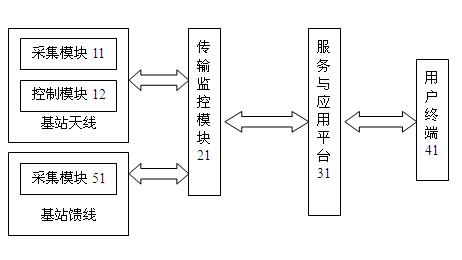
[0051] figure 1 The composition diagram of the base station antenna adjustment system provided by the embodiment of the present invention, as shown in figure 1 As shown, the system includes: antenna acquisition module 11, control module 12, feeder acquisition module 51, monitoring transmission terminal 21, service and application platform 31 and user terminal 41, wherein each base station antenna is provided with an acquisition module and a The control module, the antenna acquisition module is composed of one or more antenna angle sensors; each base station feeder is provided with an acquisition module, and the feeder acquisition module is composed of one or more feeder performance sensors, wherein:

[0052] Acquisition module 11: includes various sensors for measuring the attitude information of the antenna, accepts the control of t...


PUM


Abstract

The invention discloses a method for adjusting and monitoring a base station antenna feeder system so as to realize the real-time monitoring of the performance of base station feeder lines, realize the real-time monitoring and remote control adjustment of the angle of each base station antenna and realize the monitoring of the performance of the feeder lines and the angle of each antenna as well as the adjustment of the angle of each antenna at any time and any place through a PC (personal computer) or a mobile terminal. An acquisition module is pre-set for each base station feeder line, wherein each acquisition module comprises one or a plurality of feeder line performance sensors; and an acquisition module and a control module are pre-set for each base station antenna, wherein each acquisition module comprises one or a plurality of antenna angle sensors. The method comprises the following steps: monitoring the performance value of the feeder line by using the acquisition module of each feeder line in a real-time or periodic manner; and monitoring the angle value of the antenna by using the acquisition module of each antenna in the real-time or periodic manner.

Description

technical field [0001] The invention relates to the technical field of antennas, in particular to a method for real-time monitoring and adjustment of a base station antenna feeder system. Background technique [0002] The quality of mobile wireless network service has become a key factor in the competition among mobile operators. The attitude (such as azimuth, electronic downtilt, mechanical downtilt, etc.) of the antenna feeder system (composed of antenna system and feeder system) of the mobile base station The performance of the mobile base station (such as standing wave ratio, etc.) directly affects the coverage and service quality of the mobile base station. The precise installation, commissioning, and use of the antenna system and the performance of the antenna system during the network planning and design of the mobile base station feeder system are important. An important factor affecting the wireless network coverage and service of mobile base stations, according to ...

Claims


Application Information

Patent Timeline
Patent Type & Authority Applications(China)
IPC IPC(8): H04W24/00H04W88/08
Inventor 陶军
Owner 苏州工业园区七星电子有限公司
Learn More