
Drive circuit of LED lamp

A technology for LED lamps and controllers, which is applied in the layout of electric lamp circuits, lighting devices, light sources, etc., can solve the problems of easily burning out LEDs, increasing current, and reducing the service life of LED lamps, so as to achieve a small footprint and improve service life. , the effect of easy installation

Active Publication Date: 2013-03-13
ZHANGJIAGANG RADIANT TECH
View PDF2 Cites 2 Cited by
  • Summary
  • Abstract
  • Description
  • Claims
  • Application Information

AI Technical Summary

Problems solved by technology

In the actual use process, the LED will generate heat during the light-emitting process, which will cause the voltage drop across the LED to change. A small voltage change will cause the current flowing through the LED to increase sharply, and it is very easy to burn out the LED, which will greatly reduce Extends the service life of the entire LED lamp

Method used


Image

  • Drive circuit of LED lamp

Examples


Embodiment Construction

[0009] Specific embodiments of the present invention will be described in detail below in conjunction with the accompanying drawings.

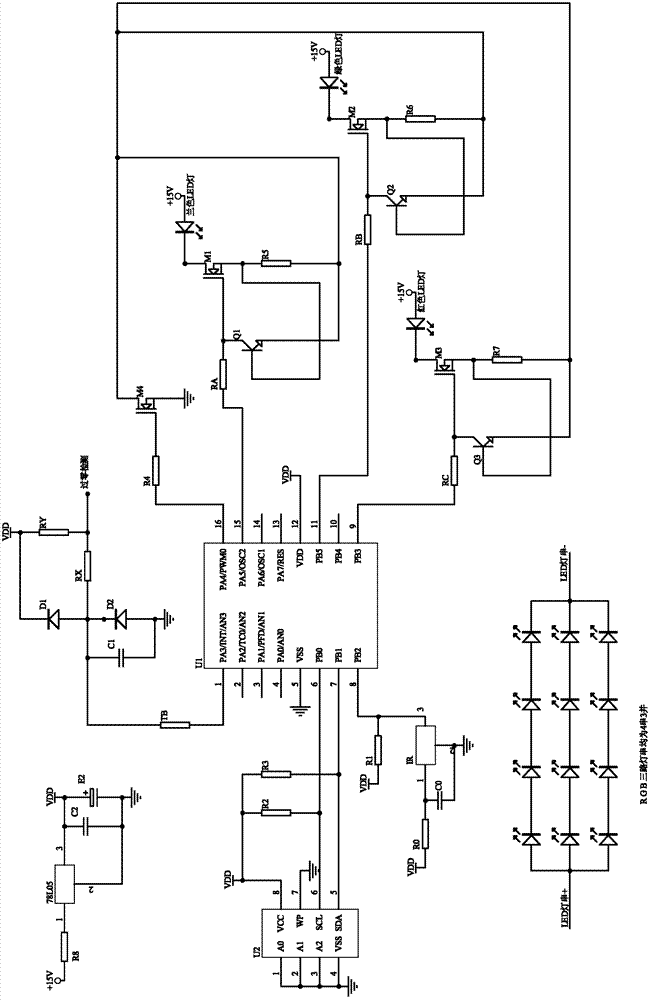
[0010] Such as figure 1 As shown, a LED light controller adopting the driving circuit of the present invention includes three sets of driving circuits of the LED light described in the present invention, and these three sets of driving circuits are respectively used to drive red, blue The red LED light is composed of four strings and three parallel red LED light strings, the blue LED light is composed of four strings and three parallel blue LED light strings, and the green LED light is composed of four strings and three parallel green LED lights Among them, the driving circuit for driving the blue LED lamp includes: a current amplification module composed of a field effect transistor (MOS transistor M1), a current limiting resistor R5 and an input resistor RA, and an electronic switch composed of a low-power high-frequency transistor Q1 Modul...


PUM


Abstract

The invention discloses a drive circuit of an LED lamp, wherein the drive circuit enables an average current passing through the LED to be basically constant when the LED lamp is lightened. The drive circuit comprises a current amplification module and an electronic switch module; a control terminal of the current amplification module is connected with a signal source through an input resistance; an output terminal of the current amplification module is connected with a power supply anode of an LED lamp through the LED lamp; an output terminal of the electronic switch module is connected with the control terminal of the current amplification module; a control terminal of the electronic switch module is connected with a negative feedback point of the current amplification module; and earth terminals of the current amplification module and the electronic switch module are both connected with the power supply cathode of the LED lamp. According to the invention, an electronic switch module and a current amplification module are cooperated with each other, so that an oscillation output of the current amplification module is realized, an LED is conductive intermittently, and service life of an LED lamp is substantially improved.

Description

technical field [0001] The present invention relates to light-emitting diodes, that is, LEDs, and in particular to an LED lamp controller formed by stringing and paralleling a plurality of LEDs. Background technique [0002] The current driving circuit of LED lights adopts the method of constant voltage and resistance current limiting. In the actual use process, the LED will generate heat during the light-emitting process, which will cause the voltage drop across the LED to change. A small voltage change will cause the current flowing through the LED to increase sharply, and it is very easy to burn out the LED, which will greatly reduce The service life of the entire LED lamp is extended. Contents of the invention [0003] The technical problem to be solved by the present invention is to provide an LED lamp controller which makes the average current flowing through the LED substantially constant when the LED lamp is turned on. [0004] In order to solve the above technic...

Claims


Application Information

Patent Timeline
Patent Type & Authority Patents(China)
IPC IPC(8): H05B37/02
Inventor 姜卫民唐仲兵顾宇栋王志勤常益峰
Owner ZHANGJIAGANG RADIANT TECH
Learn More