Contact image sensor, multi-angle optical characteristic detection method and device

A technology of optical features and detection devices, which is applied in the direction of instruments, character and pattern recognition, and banknote authenticity inspection, etc., can solve the problems of large size of CMOS or CCD camera, affect the recognition effect of color-changing ink, and increase equipment design requirements, etc., to achieve Small size, convenient equipment assembly, and compact structure

Inactive Publication Date: 2012-02-01
BEIJING NUFRONT SOFTWARE SCI TECH
View PDF0 Cites 2 Cited by
  • Summary
  • Abstract
  • Description
  • Claims
  • Application Information

AI Technical Summary

Problems solved by technology

[0012] Second, due to the banknotes of different countries and different currencies, the positions of the multi-angle optical feature areas on the banknotes are different, so a set of equipment can only be applied to one or several banknotes of a certain country Multi-angle Optical Feature Region Detection
[0013] Third, because the focal length of the camera using CMOS or CCD is relatively large, a certain shooting distance is required to shoot a certain range of field of view, so the volume required for the entire shooting device is often relatively large
This also ultimately affects the recognition effect of the color-changing ink
[0016] Moreover, due to different currencies, the positions of the banknotes where the multi-angle optical feature areas are different, and CMOS or CCD devices must be installed on the positions of the multi-angle optical feature areas, so the multi-angle optical feature areas are not in the same position. banknotes that can only be identified by multiple different devices
When a new version of banknotes is issued, if the position of the multi-angle optical feature area changes, the original equipment must be redesigned and updated for hardware
[0017] In addition, the CMOS or CCD camera requires a large volume, and for pointing, inspection, and sorting equipment with a very compact internal design, it will undoubtedly greatly increase the design requirements of the equipment and increase the overall volume of the entire equipment.

Method used


Image

  • Contact image sensor, multi-angle optical characteristic detection method and device
  • Contact image sensor, multi-angle optical characteristic detection method and device
  • Contact image sensor, multi-angle optical characteristic detection method and device

Examples


Embodiment 1

[0061] The embodiment of the present invention provides two detection methods of multi-angle optical features, which can detect and identify multi-angle optical features on banknotes, bills or other printed matter.

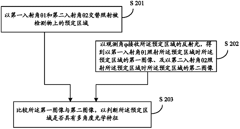
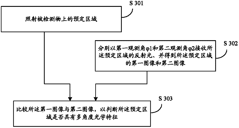
[0062] refer to figure 2 , the first multi-angle optical feature detection method provided in Embodiment 1 of the present invention includes the following steps:

[0063] S201. Alternately irradiate a predetermined area on the object to be detected with a first incident angle θ1 and a second incident angle θ2; the first incident angle θ1 and the second incident angle θ2 are not equal.

[0064] S202. Receive the reflected light of the predetermined area at the observation angle φ, and obtain the first image of the predetermined area when the predetermined area is irradiated with the first incident angle θ1, and when the predetermined area is irradiated with the second incident angle θ2 A second image of the predetermined area.

[0065] The above-mentioned first ...

Embodiment 2

[0080] Figure 4 It is a schematic structural diagram of the multi-angle optical feature detection device provided in Embodiment 2 of the present invention.

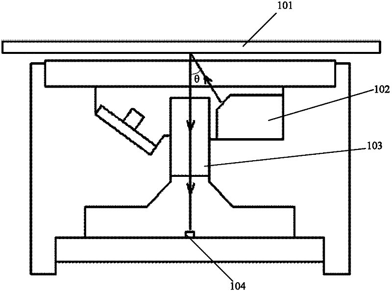
[0081] Such as Figure 4 As shown, the multi-angle optical feature detection device includes a CIS and a recognition unit ( Figure 4 Not shown in ), wherein the CIS includes alternately lit light sources 302a, 302b, lenses 303 and photoelectric conversion chips 304.

[0082] The light source 302a and the light source 302b are arranged on both sides of the lens 303 .

[0083] The light source 302a illuminates a predetermined area on the object to be detected 301 at a first incident angle θ1 when turned on.

[0084] The light source 302b illuminates a predetermined area on the object to be detected 301 at the second incident angle θ2 when turned on.

[0085] In the second embodiment, the first incident angle θ1 and the second incident angle θ2 are not equal.

[0086] In order to enable the predetermined area on the d...

Embodiment 3

[0093] Figure 5 It is a schematic structural diagram of another multi-angle optical feature detection device provided in Embodiment 3 of the present invention.

[0094] Figure 5 The difference between the shown CIS and the multi-angle optical feature detection device in Embodiment 2 is that in the multi-angle optical feature detection device provided in Embodiment 3, the two light sources 402a and 402b in the CIS are arranged on the same side of the lens 403, The lens 403 receives the reflected light in a predetermined area at an observation angle φ, and guides it into the photoelectric conversion chip 404, where the observation angle φ is greater than 0 degrees, that is, the lens 403 and the photoelectric conversion chip 404 are arranged obliquely to the plane of the detected object 401 .

[0095] The two light sources 402a and 402b are installed on the same side of the lens 403, which allows the lens 403 to have a certain inclination angle, so that the light reflected by ...


PUM


Abstract

The invention discloses a multi-angle optical characteristic detection method, which comprises the following steps of: acquiring two images of a predetermined area on a detected object from predetermined angles theta1 and theta2 respectively; and comparing the two images to judge whether the predetermined area has multi-angle optical characteristics. The invention also provides a contact image sensor (CIS), a multi-angle optical characteristic detection device using the CIS and inspection equipment using the detection device. The CIS, the multi-angle optical characteristic detection method and the multi-angle optical characteristic detection device have the advantages of high detection and identification rate and stable and reliable performance.

Description

[0001] This application claims that the application date is November 02, 2010, the application number is 201010533349.3, and the invention name is a multi-angle optical feature detection method and device. The priority of the previous application, the entire content of the previous application has been published in this application reflected in the application. [0002] technical field [0003] The invention relates to the field of optoelectronic technology, in particular to a contact image sensor (CIS, Contact Image Sensor), a multi-angle optical feature detection method and device. Background technique [0004] The multi-angle optical feature means that when the light is irradiated from different angles, or the observed object is observed from different angles, the observed object presents different image characteristics. The image seen by the printed product made by multi-angle optical feature technology has a dynamic changing effect, which cannot be reproduced by hig...

Claims


Application Information

Patent Timeline
Patent Type & Authority Applications(China)
IPC IPC(8): G07D7/20
CPCG07D7/121
Inventor 陈新万成凯唐辉
Owner BEIJING NUFRONT SOFTWARE SCI TECH
Why Eureka
Try Eureka