

Electron accelerator
An electron accelerator and electron acceleration technology, which is applied in DC voltage accelerators, electrical components, accelerators, etc., can solve the problems of lower production efficiency, high price, and large beam extraction window, so as to improve production efficiency and reduce production and operation. The effect of simple cost and trouble repair
Active Publication Date: 2012-02-01
江苏久瑞高能电子有限公司
View PDF8 Cites 15 Cited by
- Summary
- Abstract
- Description
- Claims
- Application Information
AI Technical Summary
Problems solved by technology
However, at this stage, the upper limit of the extraction density of the electron beam extraction window is about 100μA/cm2. To extract a high-current electron beam of more than 1A, the beam extraction window must be made very large, and 1A needs 10000cm 2 If it is a window with a width of 20cm, the length and height are close to 500cm, which is very large and expensive
As far as a single electron gun is concerned, its long-term continuous emission capability cannot reach 1A, and it is also limited by the intensity of the electron beam accelerated by the accelerator tube, so the utilization rate of the high-voltage power supply capacity of a single power supply with a single electron beam unit is very low
[0004] The existence of the above problems led to the emergence of a single high-voltage power supply that supplies power to two electronic acceleration systems through a high-voltage distributor
Method used
View moreImage
Smart ImageViewing Examples

Examples
 PUM
 Abstract
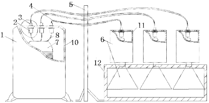
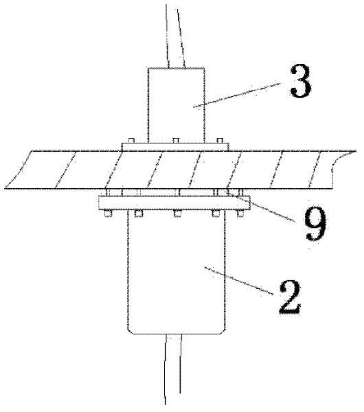
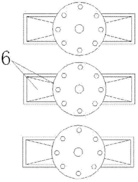
The invention relates to an electron accelerator which comprises a direct-current high-voltage power supply and a plurality of electro acceleration units. The electron accelerator is characterized in that the direct-current high-voltage power supply is connected with the electron acceleration units through a direct-current high-voltage insulation cable. One high-voltage power supply is provided with the electron acceleration units, thus the electron accelerator realizes the eduction of oversized beams of electron beams, is convenient for realization of modular design of the electron acceleration units, and has the advantages of being simple in maintaining failures, reducing overhaul time and operation time and improving production efficiency because the electron acceleration units can move freely relative to the high-voltage power supply and one electron acceleration unit can independently operate or the electron acceleration units can simultaneously operate.
Description
technical field [0001] The invention relates to an electron accelerator, specifically designing the technical field of connection between a single high-voltage power supply and multiple electron acceleration units. Background technique [0002] The electron beam irradiation processing industry is a new technology developed on the basis of the agricultural application of nuclear technology, and it is an important industry with remarkable economic and social benefits in the civilian use of nuclear technology. Electron beam irradiation processing is the process of processing substances and materials by using the physical, chemical and biological effects of the interaction between ionizing radiation (electron beams produced by electron irradiation accelerators) and substances. Up to now, electron beam irradiation processing mainly includes irradiated chemical applications, irradiated food and pharmaceutical applications, medical supplies disinfection and sterilization, and radi...
Claims
Login to View More Application Information
Patent Timeline
 IPC IPC(8): H05H5/00H05H5/02
Inventor何小海贾朝伟刘平李琦曾利王静
Owner江苏久瑞高能电子有限公司