A pumping unit driven by a cylindrical linear motor

A linear motor, cylindrical technology, used in natural gas, coal bed methane extraction equipment, petroleum fields, can solve problems such as poor effect, large starting torque, and large speed unevenness

Active Publication Date: 2018-01-09
华鹰云智(深圳)技术有限公司
View PDF5 Cites 0 Cited by
  • Summary
  • Abstract
  • Description
  • Claims
  • Application Information

AI Technical Summary

Problems solved by technology

The beam pumping unit is the main model currently used, but it has problems such as large speed unevenness, large starting torque, poor balance effect, difficult adjustment of stroke and stroke times, many intermediate links, and low system efficiency.
In response to these problems, around the theme of high efficiency and energy saving, there have been beamless pumping units such as chain pumping units, vertical drum pumping units, belt pumping units, and linear motor pumping units. However, it has not solved the problem fundamentally, and the effect is not good; among them, the mover of the existing linear motor pumping unit is still driven by a wire rope around the pulley, that is, the sky wheel, and the sucker rod is balanced by a balance weight. However, the structure is complicated, the service life of the whole machine is shorter than that of the beam pumping unit, the efficiency is low and the safety is poor, and the potential of the linear motor drive cannot be fully utilized.
The invention patent with application number 201410229797.2 discloses a linear motor direct drive pumping unit, which mainly uses a flat-plate linear motor as the driving source. The energy storage spring is located outside the linear motor mover. The configuration relationship between the energy storage spring and the mover is yet to be determined. Improve

Method used


Image

  • A pumping unit driven by a cylindrical linear motor
  • A pumping unit driven by a cylindrical linear motor
  • A pumping unit driven by a cylindrical linear motor

Examples


Embodiment 1

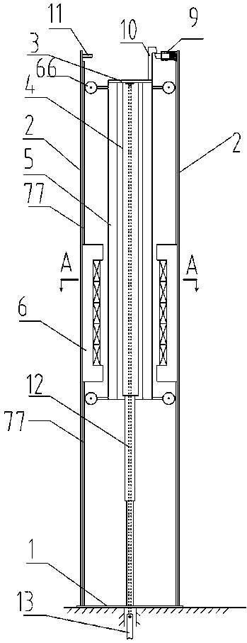
[0029] A pumping unit driven by a cylindrical linear motor, such as figure 1 , 2 . Locate the guiding device, the braking device, the sucker rod connector 12 and the sucker rod 13.

[0030] For the well-known linear motor, the general definition: the side with the armature winding is called the primary of the linear motor, and the side with the magnet or induction plate is called the secondary of the linear motor. Also defined: the moving part is the mover of the linear motor, and the fixed Part is a linear motor stator. According to the length of the mover and stator, it can be divided into two categories: long mover, short stator and short mover and long stator. The working principle of the linear motor is: a current is passed into the primary winding of the linear motor to generate a traveling wave magnetic field that can move relative to the magnet or the induction plate. In addition, the cylindrical linear motor can be converted from the flat linear motor by bending i...

Embodiment 2

[0041] Such as Figure 4 As shown, a cylindrical linear motor-driven pumping unit, the linear motor drive device can also adopt the linear motor primary movement, secondary fixed arrangement, the mover armature winding part is relatively short, the stator permanent magnet Or the reaction plate is longer (also known as short mover, long stator structure). The stator length should not be less than the sum of the mover length and stroke length. The upper end and lower end of the linear motor mover 5 are respectively provided with an upper extension sleeve 44 and a lower extension sleeve 45 having the same outer diameter as the linear motor mover, and the upper end of the upper extension sleeve 44 and the lower end of the lower extension sleeve 45 are respectively provided with Multiple sets of guiding and positioning devices ensure the mechanical air gap between the mover 5 of the linear motor and the stator of the linear motor so that the two can move with each other. Setting ...

Embodiment 3

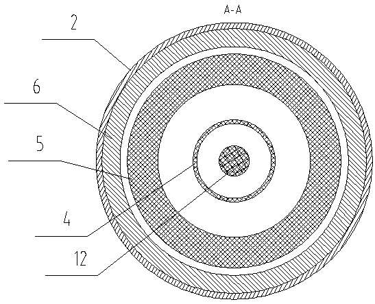
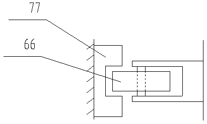
[0044] Such as Figure 5 As shown, four sets of guiding and positioning devices are symmetrically arranged on the upper end and the lower end of the cylindrical linear motor rotor 5, respectively, and four stator slots 65 are provided in the axial direction on the circumference of the linear motor stator 6, and the linear motor stator 6 is divided into equal parts. It is four circular arc segments, and the parts of the guiding and positioning device are accommodated in the four stator slots, that is, the guiding and positioning device needs to pass through the linear motor stator 6. The positioning and guiding device of the linear motor mover 5 described in this embodiment is as follows: Figure 8 As shown, it can be completed by guide wheels and linear guide grooves, or as Figure 9 It is completed by linear guide rails and sliders, and can also be completed by T-shaped guide rails 771 and concave guide wheels 772. The specific positioning is as in Embodiment 1.

[0045] The...


PUM


Abstract

The invention provides an oil pumping unit of which a sucker rod is directly driven by a linear motor. The oil pumping unit comprises a rack, a linear motor driving device, a single-stage or multi-stage telescopic machine or a gas spring energy storage device, a linear motor rotor, a sucker rod connector and the like, wherein the linear motor driving device, the single-stage or multi-stage telescopic machine or the gas spring energy storage device, the linear motor rotor, the sucker rod connector and the like are arranged on the rack. The oil pumping unit cancels the connection of elastic pieces or radial components such as hair braids, steel wire ropes and belts for an original oil pumping unit, adopts a direct balance mode, and thus cancels the reversing device (head sheave) of an existing non-beam oil pumping unit, so that the efficiency of the oil pumping unit is further improved, the height and weight of the oil pumping unit are reduced, and the service life, reliability and safety of the oil pumping unit are improved.

Description

technical field [0001] The invention belongs to the field of extraction equipment for oil, natural gas and coal bed methane, in particular to an oil pump driven by a cylindrical linear motor using single-stage and multi-stage retractable spring accumulators. Background technique [0002] The pumping unit is an important equipment for the exploitation of oil, natural gas and coalbed methane, and it is required to operate efficiently and stably for a long time under various environmental and climatic conditions. There are two types of pumping units commonly used at present, which can be divided into beam pumping units and beam pumping units without beams. The beam pumping unit is the main model currently used, but it has problems such as large speed unevenness, large starting torque, poor balance effect, difficult adjustment of stroke and stroke times, many intermediate links, and low system efficiency. In response to these problems, around the theme of high efficiency and en...

Claims


Application Information

Patent Timeline
Patent Type & Authority Patents(China)
IPC IPC(8): E21B43/00
CPCE21B43/121H02K7/14
Inventor 汪旭东许宝玉孙浩许孝卓封海潮王玉琳
Owner 华鹰云智(深圳)技术有限公司
Why Eureka
Try Eureka