A direct contact compound heat exchange system

A heat exchange system and compound technology, which is applied in the field of direct contact compound heat exchange system, can solve problems such as the utilization gap of low-temperature waste heat resources, and achieve the effects of preventing high-temperature thermal decomposition, preventing safety accidents, and simplifying the structure.

Active Publication Date: 2020-08-11
KUNMING UNIV OF SCI & TECH
View PDF4 Cites 0 Cited by
  • Summary
  • Abstract
  • Description
  • Claims
  • Application Information

AI Technical Summary

Problems solved by technology

However, compared with developed countries, there is still a certain gap in the utilization of low-temperature waste heat resources in the industrial field.

Method used


Image

  • A direct contact compound heat exchange system

Examples


Embodiment 1

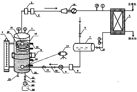
[0020] A direct contact compound heat exchange system, such as figure 1 Shown, including heat exchanger 1, liquid level meter 2, gas-liquid separator 3, gas mass flow meter 4, plate condenser 5, shut-off valve I 6, vacuum liquid storage tank 7, liquid mass flow meter 8, centrifugal pump 9 , Check valve 10, manual control valve 11, nozzle 12, 7 thermocouples 13, spiral channel inlet 14, 2 visible windows 15, 12-electrode electrical capacitance tomography system (ECT) 16, high-speed camera 17, turbine power generation Machine 18, spiral channel outlet 19, spiral channel 20, stop valve Ⅱ 21, heat transfer oil inlet 22, heat transfer oil outlet 23, valve 24, pump 25, heat transfer oil tank 26, multiple pressure gauges, multiple thermometers;

[0021] A spiral channel 20 is arranged inside the heat exchanger 1, the diameter of the spiral channel 20 is 0.8 of the inner diameter of the heat exchanger 1, the spiral channel inlet 14 is arranged on the upper part of the heat exchanger 1 an...

Embodiment 2

[0028] A direct contact compound heat exchange system, in which the spiral channels 20 of Example 1 are increased to two, the spiral channels 20 have the same inner diameter, which is 0.5 of the inner diameter of the heat exchanger 1, and the two spiral pipes are coaxial with the heat exchanger 1. The two spiral pipes are respectively provided with a spiral channel inlet 14 and a spiral channel outlet 19. The spiral channel 20 is a steel spiral channel. The heating medium connected to the spiral channel 20 is hot wastewater. The flow inlet of the hot wastewater is 3L / min. The inlet temperature of the hot waste water at the channel inlet 14 is 100°C, and the outlet temperature is 20°C. The other components and the connection relationship between the components are the same as in Embodiment 1.

[0029] Experiments were conducted with two different devices, the heat exchange system of this embodiment and the conventional direct contact heat exchanger. The experimental results show th...

Embodiment 3

[0031] A direct contact compound heat exchange system. The spiral channels 20 of Example 1 are increased to four. The four spiral channels 20 have the same inner diameter, which is 0.6 of the inner diameter of the heat exchanger 1. The four spiral pipes are all connected to the heat exchanger. 1 Coaxially arranged, each spiral pipe is provided with a spiral channel inlet 14 and a spiral channel outlet 19 respectively. The spiral channel 20 is a steel spiral channel. The heating medium connected by the two spiral channels 20 is hot wastewater. The inlet flow rate of the hot wastewater is 3L / min, the inlet temperature of the hot waste water at the inlet 14 of the spiral channel is 100°C, and the outlet temperature is both 20°C. The heating medium connected to the remaining two spiral channels 20 is hot flue gas, and the hot flue gas flow inlet is 5L / min. The inlet temperature of the hot flue gas at the inlet 14 is 100°C, and the outlet temperature is 20°C. The other components an...


PUM


Abstract

The invention discloses a direct contact composite type heat exchange system. The system comprises a heat exchanger, a liquid level apparatus, a gas and liquid separator, a gas mass flowmeter, a platetype condenser, a stop valve I, a vacuum liquid storage tank, a liquid mass flowmeter, a centrifugal pump, a check valve, a manual adjusting valve, a nozzle, a turbine generator, a spiral channel, astop valve II, a heat conduction oil inlet, a heat conduction oil outlet, a valve, a pump, a heat conduction oil storage tank, multiple pressure meters, and multiple thermometers. Heat media enter thespiral channel, the reverse flow manner from top to bottom is adopted for transferring heat to matter in the heat exchanger, the stirring in the heat exchanger is increased, the two-phase flow innerheat transfer is greatly reinforced, and when the system is applied to the power generation field, the power generation efficiency is higher; and compared with an outer heating device of a common direct contact heat exchanger, the inner spiral channel makes direct contact with the heat exchanger, the heat exchange process can be reduced, the fire losses are reduced, and the energy use rate is improved.

Description

Technical field [0001] The invention relates to a direct contact compound heat exchange system, which belongs to the field of waste heat utilization. Background technique [0002] Energy-saving and emission-reduction technologies have received more and more attention in areas with high energy consumption such as thermal engineering, refrigeration, and power industries, and are especially widely used in heat exchangers, refrigerators, power station boilers and other equipment. Significant results have been achieved in the utilization of waste heat resources in my country's industrial fields, especially high and medium temperature waste heat resources. However, compared with developed countries, there is still a certain gap in the utilization of low-temperature waste heat resources in the industrial field. With the continuous deepening of energy-saving work, the utilization of low-temperature waste heat resources has increasingly become a hot and difficult point in energy-saving w...

Claims


Application Information

Patent Timeline
Patent Type & Authority Patents(China)
IPC IPC(8): F28C3/04F28D7/02F28F13/06F28F27/00F22B37/26
Inventor 徐建新郭雅欣肖清泰黄峻伟王华
Owner KUNMING UNIV OF SCI & TECH
Why Eureka
Try Eureka