Structure for fastening metallic plate parts together

A technology for fixing structures and metal plates, which is applied in the direction of metal casings, closed casings, circuits, etc., can solve problems such as fewer fixed parts and abnormal sounds, and achieve the effects of suppressing abnormal sounds, preventing slack, and realizing assembly and disassembly Effect

Inactive Publication Date: 2012-02-01
MITSUBISHI ELECTRIC CORP
View PDF1 Cites 9 Cited by
  • Summary
  • Abstract
  • Description
  • Claims
  • Application Information

AI Technical Summary

Problems solved by technology

Therefore, it is considered to reduce the number of screws used, but the number of fixed parts is reduced, so there are technical problems such as abnormal sound when vibrating.

Method used


Image

  • Structure for fastening metallic plate parts together
  • Structure for fastening metallic plate parts together
  • Structure for fastening metallic plate parts together

Examples


Embodiment approach 1

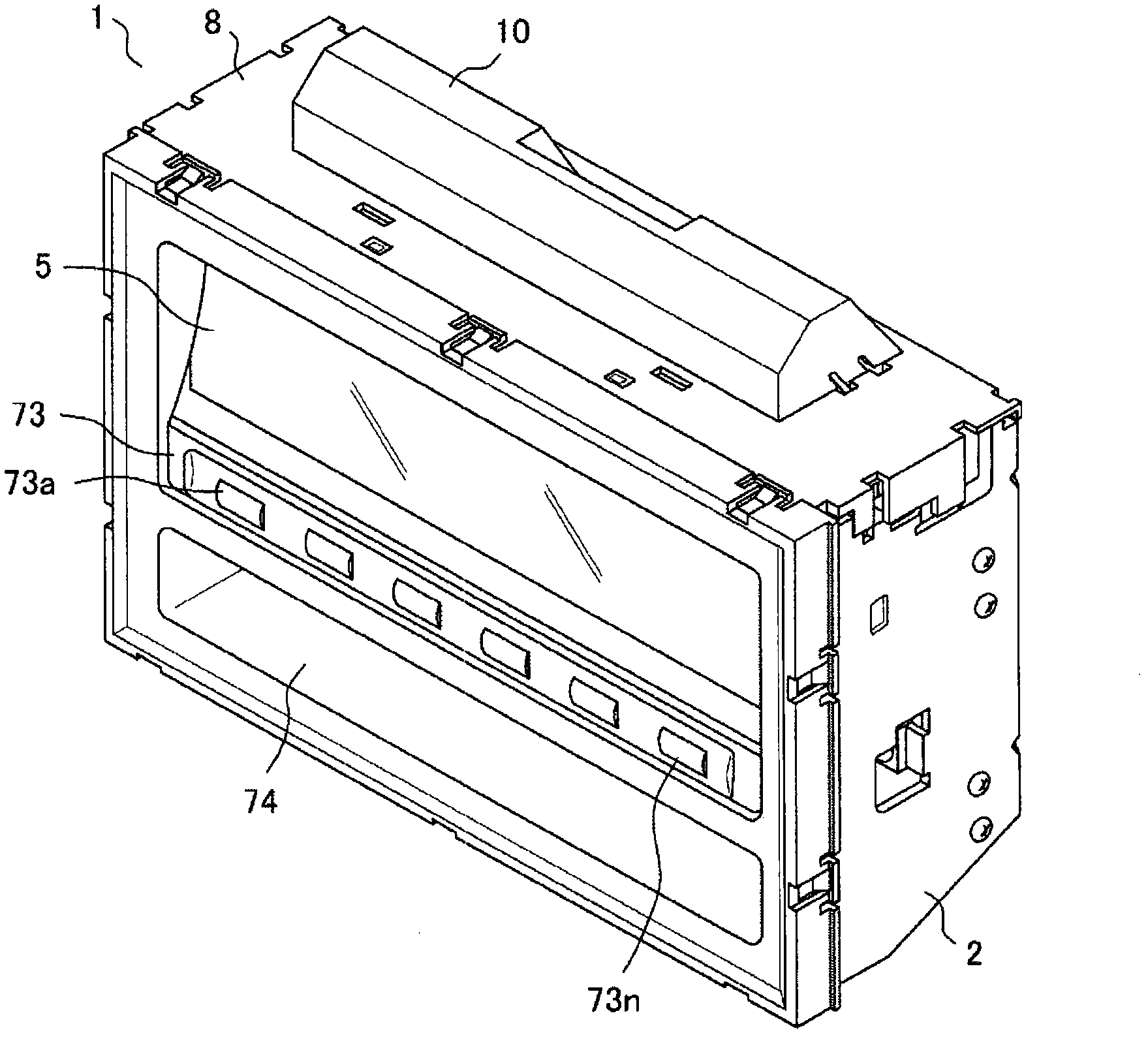
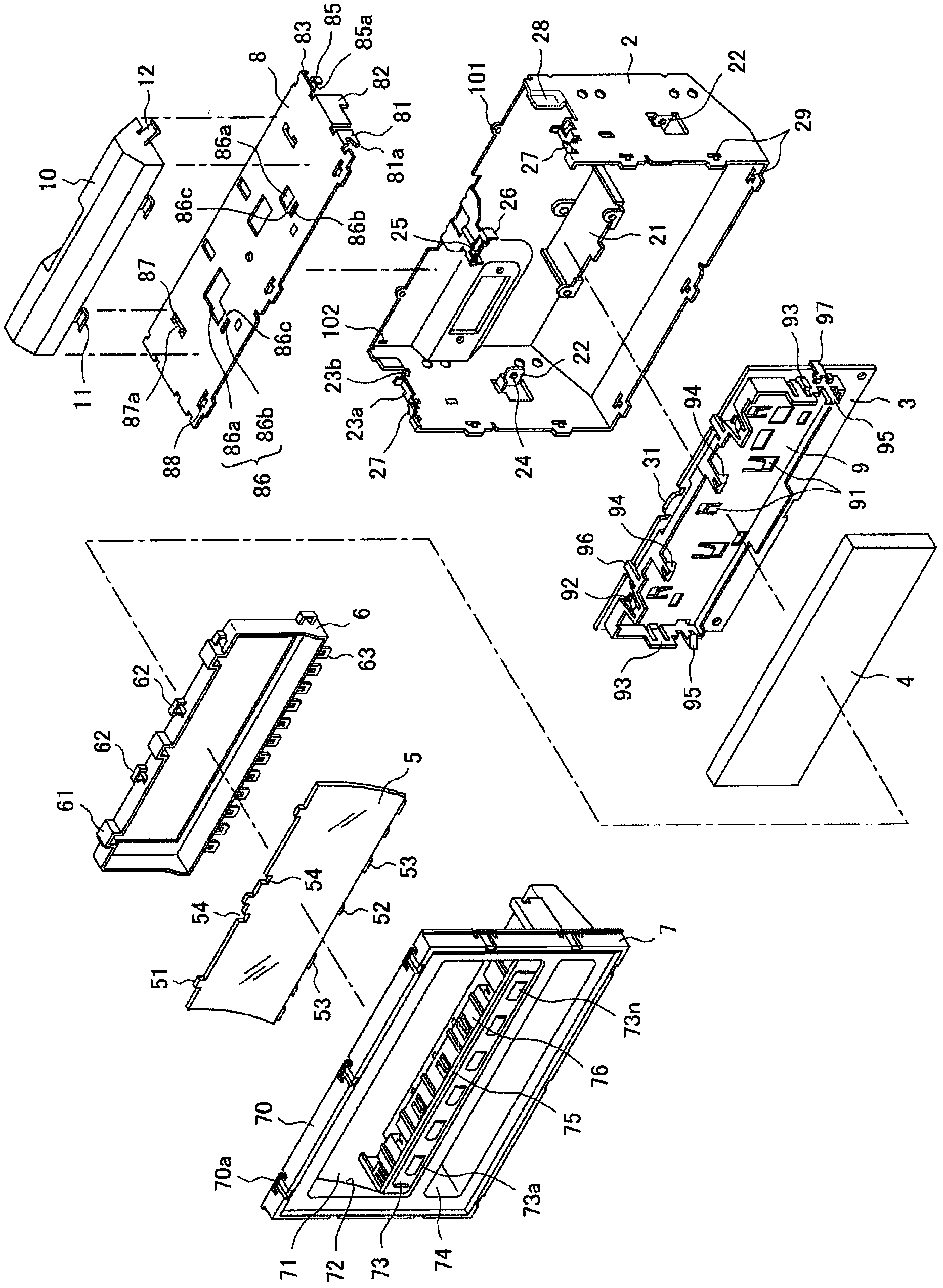
[0022] Hereinafter, the fixing structure of the metal plate parts of this invention is demonstrated based on drawing. First, according to figure 1 , figure 2 An outline of an electronic device using the fixing structure of metal plate parts of the present invention will be described. This electronic device 1 has: a box-shaped hollow casing 2 as a first metal plate part; a substrate 3 assembled inside the casing 2; a display 4 assembled on the substrate 3; a filter arranged opposite to the display 4 The device 5 and the cover 6 are installed together and assembled into the panel 7 in the casing 2; and the cover 8 as a second metal plate part that covers the opening of the casing 2 after all the above-mentioned components are assembled. The expressions of the upper and lower panels, front and rear panels, and left and right side panels in the following description are based on the state where the electronic device is installed at the use position.

[0023] The housing 2 incl...


PUM


Abstract

A chassis 2 as a first sheet-metal part has an L-shaped hooking section 27 formed at a cover mounting opening end of each side plate thereof, and an assembly guide section 28 dimpling inwardly the opening end of the chassis 2 by the thickness of a cover 8; the cover 8 as a second sheet-metal part has a hooking claw 81 extending from each side edge of the cover to the mounting side thereof and engaging with the L-shaped hooking section 27, and a guide lug 82 engaging with the assembly guide section 28, wherein an engaging claw 85 and an engaging hole 102, and a tapped hole 101 and a screw passing-through hole 84 are relatively provided on the abutment faces between the chassis 2 and the cover 8, respectively.

Description

technical field [0001] The present invention relates to a fixing structure of metal plate parts in which a cover of a metal plate part is assembled to a casing (base) of the metal plate part in electric equipment. Background technique [0002] In electrical equipment installed in mobile bodies such as automobiles, for example, when a cover of a sheet metal part is assembled to a casing of the sheet metal part, the casing and the cover, that is, the sheet metal part, are fixed to each other with screws. Therefore, a large number of screws are used, it takes a long time for assembly, and the disassembly property is also deteriorated. Therefore, it is considered to reduce the number of screws used, but the number of fixed parts is reduced, so there are technical problems such as abnormal sound during vibration. [0003] In addition, in the image forming apparatus of Patent Document 1, a structure is disclosed in which the inside of the original conveying device can be exposed ...

Claims


Application Information

Patent Timeline
Patent Type & Authority Applications(China)
IPC IPC(8): H05K5/04
CPCH05K5/0013H05K5/0008Y10T403/7045
Inventor 广田秀行
Owner MITSUBISHI ELECTRIC CORP
Why Eureka
Try Eureka