Supporting method of side template at later casting zone of floor part

A technology of post-casting strips and lateral formwork, which is applied in the field preparation of formwork/formwork/work frame, building components, construction, etc., and can solve the problems of heavy workload of on-site workers, large amount of chiseling in the later stage, and large waste of formwork and other problems, to achieve the effects of simple and fast support and demolition construction, less cutting and chiseling in the later stage, and better appearance of concrete sections

Inactive Publication Date: 2012-02-08
李国庆
View PDF0 Cites 1 Cited by
  • Summary
  • Abstract
  • Description
  • Claims
  • Application Information

AI Technical Summary

Problems solved by technology

[0002] In the construction of construction projects, it is often necessary to set up concrete post-pouring belts on walls, beams, floors and other parts. Among them, the formwork support on both sides of the post-casting belts on the floor slabs is generally used in the existing construction method to cut small gaps in the strip-shaped wooden formwork. Stuff it into the upper and lower rows of steel bars, insert the steel bars at the gap, place wooden squares on the steel bars, and fix the strip wooden formwork and wooden squares firmly, which not only completes the formwork process; but also uses dense mesh steel wire mesh or quick and easy-to-detach mesh As a concrete baffle, it is fixed in the upper and lower rows of steel bars and used as the formwork on both sides of the post-casting belt. After the concrete is poured, it will not be dismantled. This method has the disadvantages of heavy workload for on-site workers, large waste of formwork, serious grout leakage, and poor appearance. There are many disadvantages such as high cost and large amount of chiseling in the later stage

Method used


Image

  • Supporting method of side template at later casting zone of floor part
  • Supporting method of side template at later casting zone of floor part
  • Supporting method of side template at later casting zone of floor part

Examples


Embodiment Construction

[0011] Below in conjunction with accompanying drawing, the present invention is described in further detail:

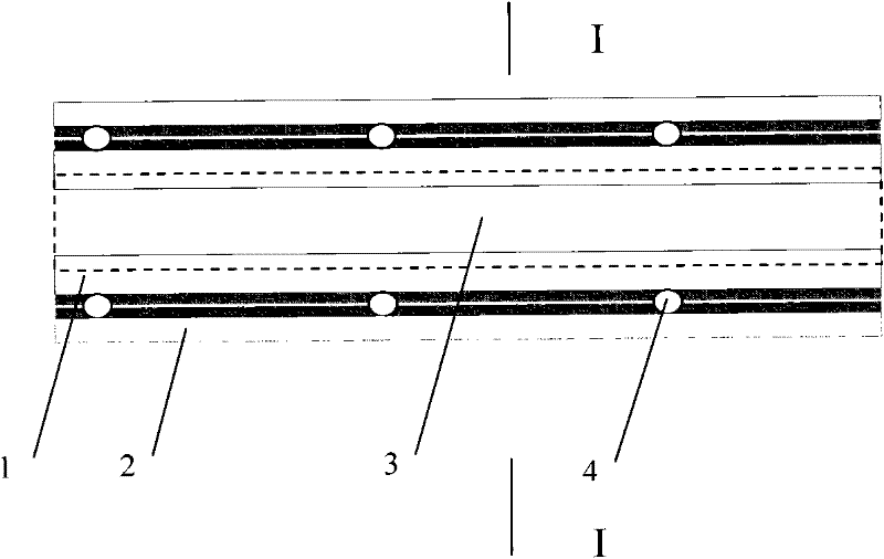
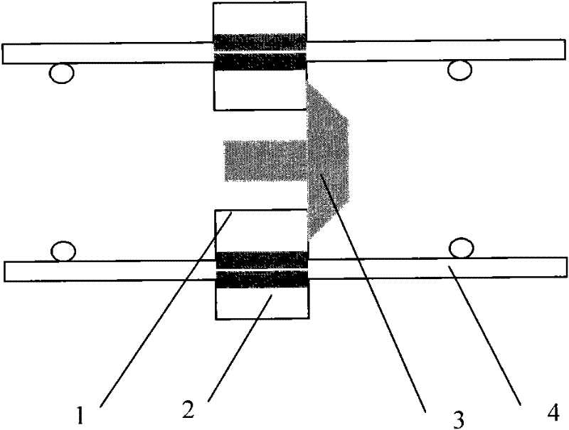
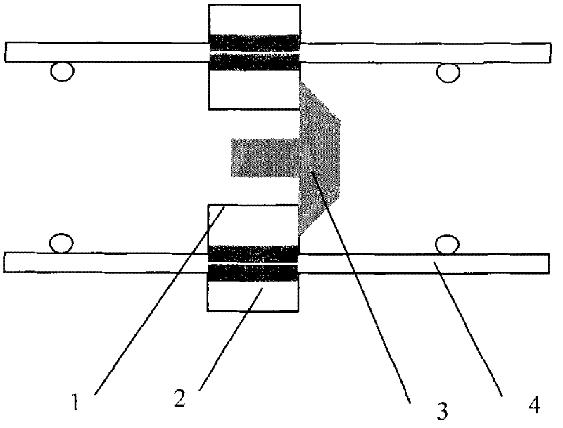
[0012] Such as figure 1 As shown, the lower composite strip 2 is placed on the lower part of the floor reinforcement 4 in the lower row, and the flexible material layer of the lower composite strip 2 is attached to one side of the floor reinforcement 4, and the upper composite strip 1 is placed on the top of the floor reinforcement 4, and the flexible material layer of the upper composite strip 1 Paste on the side of the floor steel bar 4, clamp and fix the hard material layer of the upper composite strip 1 and the lower composite strip 2, so that the lower row of floor steel bars 4 is wrapped by the upper composite strip 1 and the lower composite strip 2 , the upper composite strip 1 flexible material layer and the lower composite strip 2 flexible material layer are also tightly fitted without gaps, and the row of steel bars on the floor is also clamped and fixed wit...


PUM


Abstract

The invention relates to a building construction method, and in particular relates to a supporting method of a side template at a later casting zone of a floor part. Upper-row and lower-row steel bars of a floor are respectively clamped and fixed by using two compound strips (one side is made of soft materials and the other side is made of hard materials) from the upper surface and the lower surface, a blocking strip is centrally placed between the upper-row steel bars and the lower-row steel bars to block the gap between the two compound strips, and the blocking strip is well fixed, and then the die supporting procedure is finished; and after the concrete is cast and initially set, the blocking strip and the compound strips are loosened and taken down, and then the die removing procedure is finished. According to the supporting method provided by the invention, the compound strips and a blocking plate produced in a standard manner are used, so that the work quantity of workers on site can be reduced, the erection and disassembly construction is simple, convenient and fast, the appearance of the concrete section is good, the slurry leakage is not easy, and the picking and chiseling at a later period are reduced; and since the compound strips and the blocking plate can be used periodically for multiple times, the cost can be reduced and a great amount of labor and the consumption of the template can be saved.

Description

technical field [0001] The invention relates to a building construction method, in particular to a method for supporting a side formwork of a post-cast belt at a floor slab. Background technique [0002] In the construction of construction projects, it is often necessary to set up concrete post-pouring belts on walls, beams, floors and other parts. Among them, the formwork support on both sides of the post-casting belts on the floor slabs is generally used in the existing construction method to cut small gaps in the strip-shaped wooden formwork. Stuff it into the upper and lower rows of steel bars, insert the steel bars at the gap, place wooden squares on the steel bars, and fix the strip wooden formwork and wooden squares firmly, which not only completes the formwork process; but also uses dense mesh steel wire mesh or quick and easy-to-detach mesh As a concrete baffle, it is fixed in the upper and lower rows of steel bars and used as the formwork on both sides of the post-...

Claims


Application Information

Patent Timeline
Patent Type & Authority Applications(China)
IPC IPC(8): E04G21/02E04G11/36E04B1/682
Inventor 李国庆
Owner 李国庆
Why Eureka
Try Eureka