Self-formed ball seat sliding sleeve

A ball seat type, sliding sleeve technology, applied in wellbore/well components, earthwork drilling, sealing/packing, etc., can solve the problem of large sliding sleeve, and achieve the effect of low accident rate, convenient use and perfect transformation

Active Publication Date: 2012-02-08
XINJIANG SINOGASOLINEEUM ENG
View PDF7 Cites 26 Cited by
  • Summary
  • Abstract
  • Description
  • Claims
  • Application Information

AI Technical Summary

Problems solved by technology

[0004] Often time research found that the primary problem to be solved is how to ensure that the sliding sleeve has a relatively large inner diameter, and N sliding sleeves can be opened in sequence by using balls of the same diameter, while the ball does not affect the output during mining

Method used


Image

  • Self-formed ball seat sliding sleeve
  • Self-formed ball seat sliding sleeve
  • Self-formed ball seat sliding sleeve

Examples


Embodiment Construction

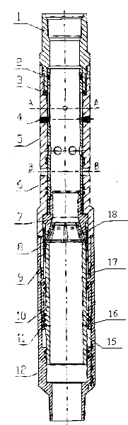
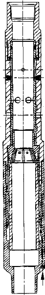
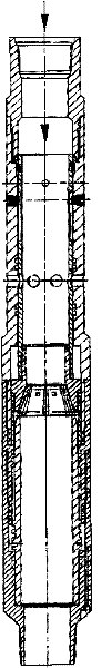
[0021] Such as Figure 1 The shown upper joint 1, split ring 2, retaining ring 3, plug-type sliding key 4, sliding key groove 13, outer cylinder 5, sliding sleeve 6, ball seat 7, self-locking sleeve 8, fixed sleeve 9, sliding mandrel 10. The way in which the shear pin 11 and the lower joint 12 are connected together completes the process of automatically generating the ball seat.

[0022] The specific working process is: connecting the upper joint 1 with the outer cylinder 5, the connecting sleeve 9, and the lower joint 12 in sequence to form the outer cover of the automatic ball seat; the internal structure has a sliding sleeve 6, a ball seat 7, a self-locking sleeve 8 and Sliding mandrel 10, one end of sliding sleeve 6 is inserted into the upper joint, and the other end is threadedly connected with ball seat 7. The claw at the front end of sliding mandrel 10 snaps into the bell mouth of ball seat 7, and connects with connecting sleeve 9 with shear pin 11 To be fixed together...


PUM


Abstract

The invention provides a self-formed ball seat sliding sleeve. The self-formed ball seat sliding sleeve comprises an upper joint (1), a split ring (2), a retaining ring (3), a screwed plug sliding key (4), an outer cylinder (5), a sliding sleeve (6), a ball seat (7), inverted V-shaped open slots (18), a self-locking sleeve (8), a fixing sleeve (9), an air cavity (19), a sliding central spindle (10), shear pins (11), shear pin holes (16), a pressure-bearing cavity (15) and a lower joint (12) which are sequentially connected together. Compared with the prior art, the self-formed ball seat sliding sleeve provided by the invention has the advantages of ensuring the same inner diameter of pipe columns, avoiding ball-throwing misoperation, achieving more perfect reformation and high efficiency, lowering accident rate and being convenient for use.

Description

technical field [0001] The invention relates to a downhole tool for oil and gas well testing and production testing, in particular to a downhole tool for segmental transformation of a horizontal well. Background technique [0002] With the progress of oil exploration and development, oil and gas well testing technology is constantly updated, and drilling horizontal wells has become the preferred production method to obtain high yield of single well. At the same time, the stimulation of heterogeneous reservoirs is becoming more and more common and in-depth. The existing horizontal well stimulation is generally a general transformation. The disadvantage of this method is that the horizontal section cannot be uniformly stimulated, and the stimulation effect is poor; Due to the limitation of the horizontal section, the multi-level fine transformation cannot be carried out, and the transformation effect is still unsatisfactory. Due to the influence of the inner diameter of the ba...

Claims


Application Information

Patent Timeline
Patent Type & Authority Applications(China)
IPC IPC(8): E21B34/06
Inventor 朱进府李志国张福祥杨向同彭建新王群琪
Owner XINJIANG SINOGASOLINEEUM ENG
Why Eureka
Try Eureka