Insulation monitor and monitoring method thereof

An insulation monitor and insulation monitoring technology, applied in the direction of instruments, measuring equipment, measuring devices, etc., can solve the problem of not being able to monitor whether the three busbars are grounded in real time, and achieve the effect of easy handling

Active Publication Date: 2013-08-07
HUAWEI TEHCHNOLOGIES CO LTD
View PDF3 Cites 0 Cited by
  • Summary
  • Abstract
  • Description
  • Claims
  • Application Information

AI Technical Summary

Problems solved by technology

[0003] In order to solve the technical problem that the traditional monitoring instrument cannot monitor whether each of the three busbars is grounded in real time, the invention provides an insulation monitoring instrument for monitoring three busbars and a monitoring method thereof

Method used


Image

  • Insulation monitor and monitoring method thereof
  • Insulation monitor and monitoring method thereof
  • Insulation monitor and monitoring method thereof

Examples


Embodiment 4

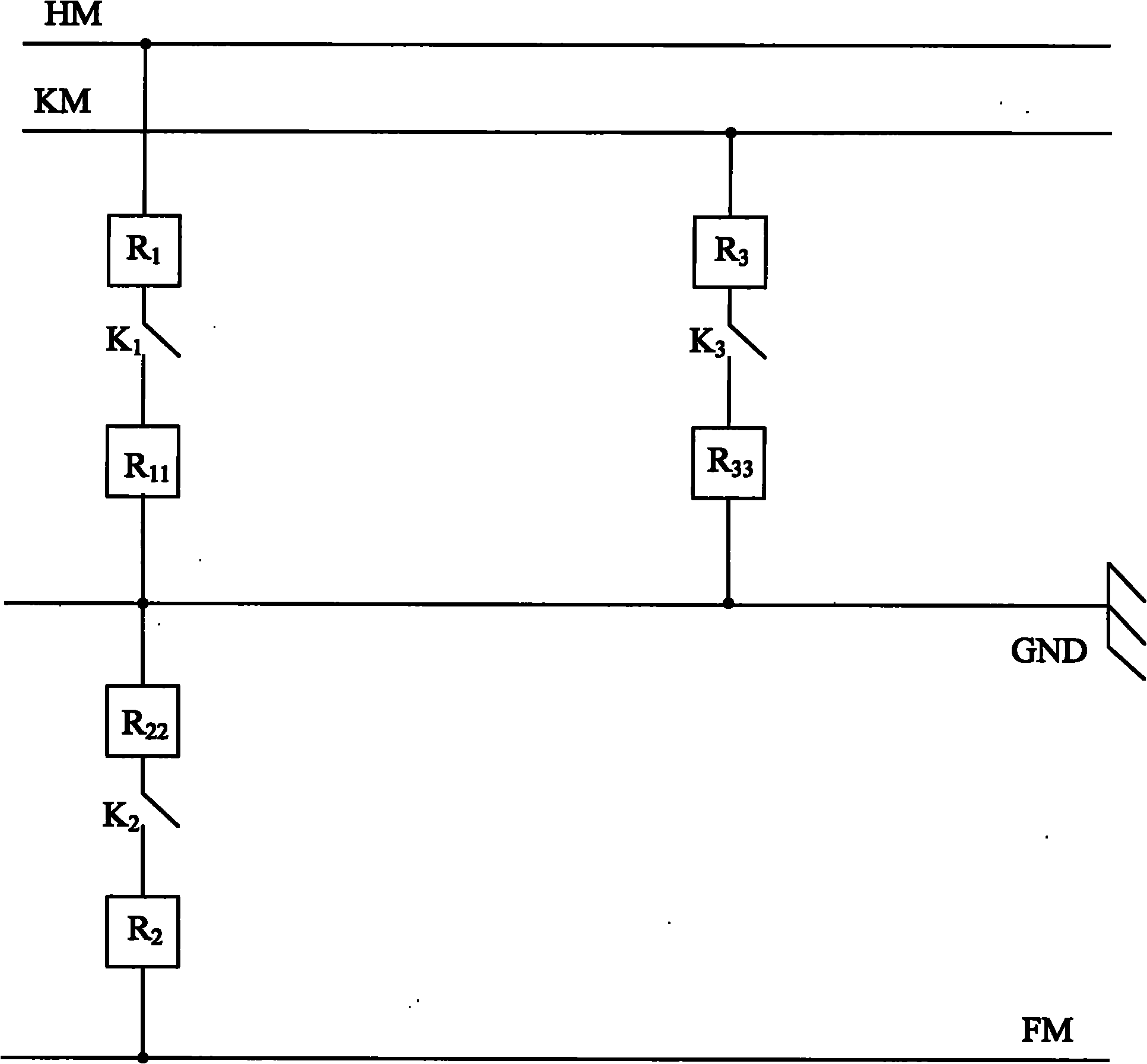
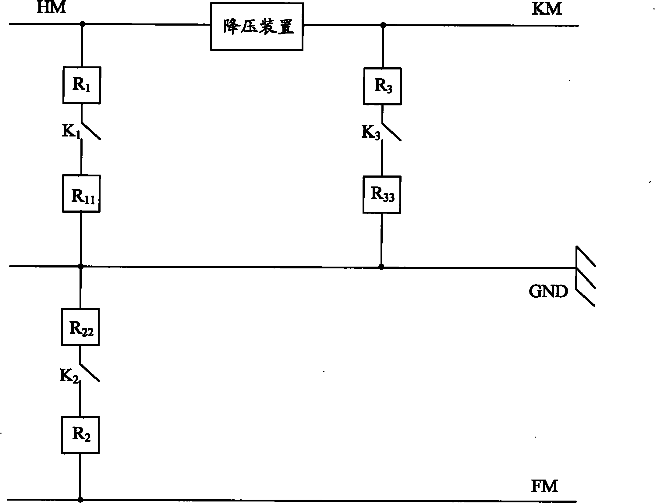
[0040] Step 20: Connect resistor R1, switch K1, and sampling resistor R11 in series from the bus bar HM to the ground line GND, and connect sampling resistor R22, switch K2, and resistor R2 in series from the ground line GND to the bus bar FM, from the bus bar KM to the ground In the direction of line GND, resistor R3, switch K3 and sampling resistor R33 are sequentially connected in series (see figure 2 ).

[0041] Step 11:

[0042] Close the switch K1 and switch K2, measure the voltage across the sampling resistors R11 and R22, and then obtain the voltage U1 between the bus HM and the bus FM through the principle of resistance voltage division;

[0043] Close the switch K2 and switch K3, measure the voltage across the sampling resistors R33 and R22, and then obtain the voltage U2 between the bus KM and the bus FM through the principle of resistance voltage division;

[0044] Close the switch K1, measure the voltage at both ends of the sampling resistor R11, and then obtai...

Embodiment 5

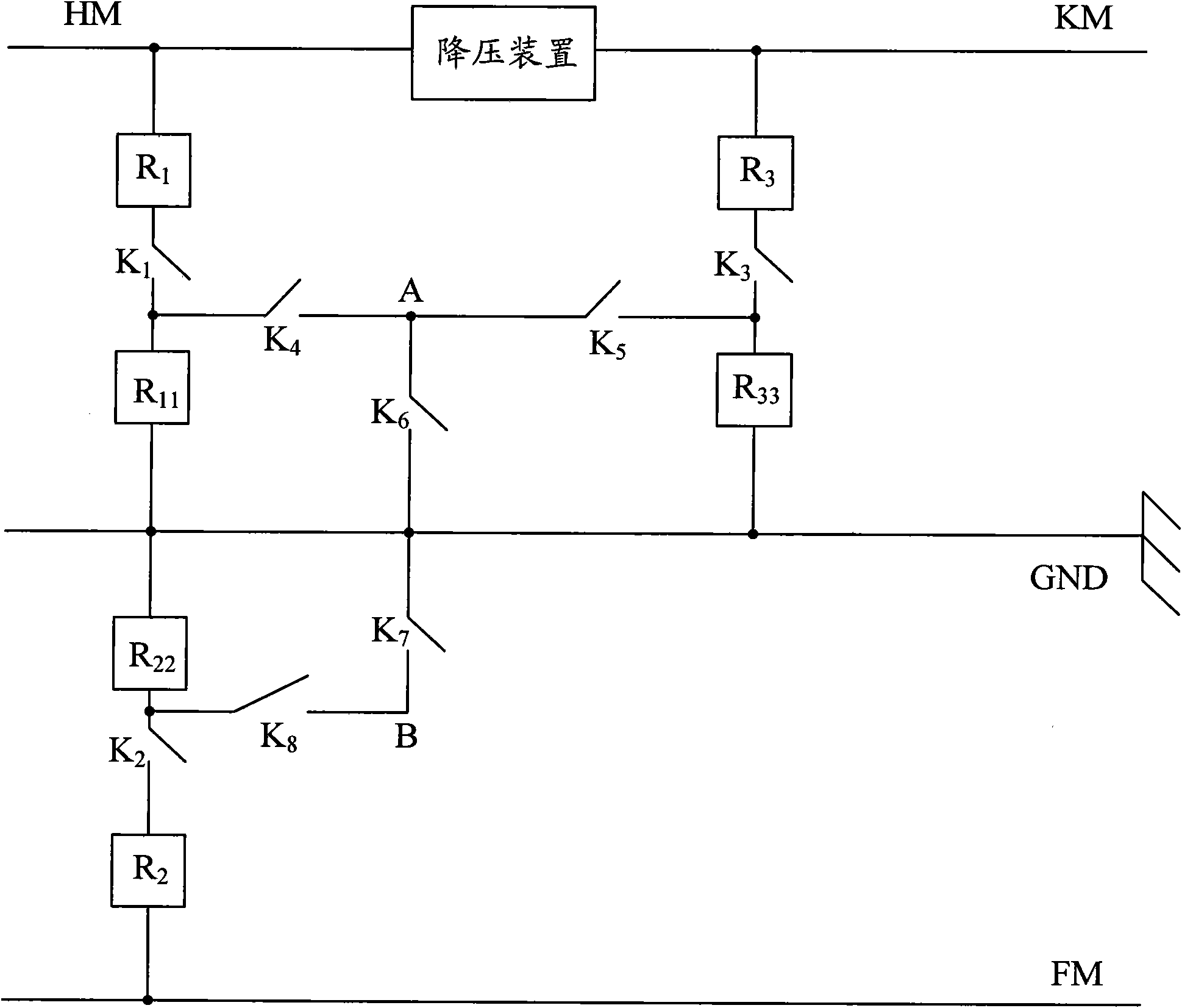
[0086] Step 20: Connect resistor R1, switch K1, and sampling resistor R11 in series from the bus bar HM to the ground line GND, connect the sampling resistor R22, switch K2, and resistor R2 in series from the ground line GND to the bus bar FM, and connect the bus bar KM to the ground A resistor R3, a switch K3 and a sampling resistor R33 are sequentially connected in series in the direction of the line GND. The busbar HM is connected to one end of the switch K1 through the resistor R1, the other end of the switch K1 is respectively connected to one end of the sampling resistor R11 and one end of the switch K4, the other end of the sampling resistor R11 is grounded to GND, and the other end of the switch K4 is respectively connected to the switch through point A. One end of K5 is connected to one end of switch K6, the other end of switch K5 is respectively connected to one end of sampling resistor R33 and one end of switch K3, the other end of sampling resistor R33 is grounded t...


PUM


Abstract

The invention provides a monitor and a monitoring method thereof. The monitor comprises a first resistor, a first switch and a first sampling resistor which are connected in series with one another from a first bus to a ground wire, a second sampling resistor, a second switch and a second resistor which are connected in series with one another from the ground wire to a third bus, and a third resistor, a third switch and a third sampling resistor which are connected in series with one another from a second bus to the ground wire; and the monitoring method comprises the following steps of: measuring voltage between the first bus and the third bus, voltage between the second bus and the third bus, voltage between the first bus and the ground wire, voltage between the second bus and the ground wire and voltage between the ground wire and the third bus; and comparing the measured voltages, and judging whether the buses are grounded according to comparison results. By the monitor and the monitoring method, a grounding state of each of the three buses of a direct current system can be monitored in real time and processed timely, so damage caused by bus grounding can be avoided.

Description

technical field [0001] The invention relates to an insulation monitor used for busbar monitoring and a monitoring method thereof. Background technique [0002] In the daily operation and maintenance of substations and abnormal handling, the most complicated thing is to find and deal with the busbar grounding in the DC system. When the busbar is grounded at one point, it will not affect the equipment system, but if it is not found and dealt with in time, once the busbar is grounded at two points, serious consequences such as short circuit, device malfunction, and refusal to operate may occur. In the existing DC system, two busbars or three busbars are commonly used. However, the current traditional monitoring instrument does not have the ability to monitor the grounding conditions of the three busbars in real time, making it difficult for operators to find which busbar is grounded in time and process it. It will bring great harm to the DC system. Contents of the invention ...

Claims


Application Information

Patent Timeline
Patent Type & Authority Patents(China)
IPC IPC(8): G01R31/02G01R27/20
Inventor 邓林旺徐旸李鑫
Owner HUAWEI TEHCHNOLOGIES CO LTD
Why Eureka
Try Eureka