
Design method of seven-segment type straight claw rotor

A design method, seven-stage technology, applied in computing, special data processing applications, instruments, etc., can solve problems such as high precision and low efficiency

Inactive Publication Date: 2012-02-08
王连智
View PDF6 Cites 8 Cited by
  • Summary
  • Abstract
  • Description
  • Claims
  • Application Information

AI Technical Summary

Problems solved by technology

[0003] The purpose of the present invention is to provide a seven-section straight-claw rotor design method to overcome the high precision of the screw-type rotor in the prior art, the processing of existing equipment cannot meet its precision requirements, and the curved-claw rotor can only be cut by wire processing, the efficiency is too low

Method used


Image

  • Design method of seven-segment type straight claw rotor
  • Design method of seven-segment type straight claw rotor
  • Design method of seven-segment type straight claw rotor

Examples


Embodiment Construction

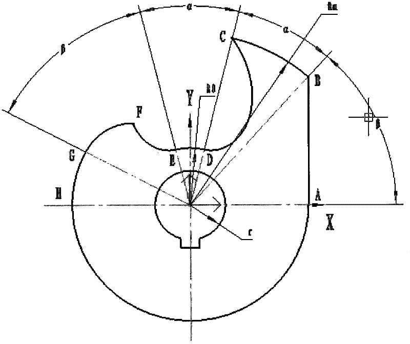
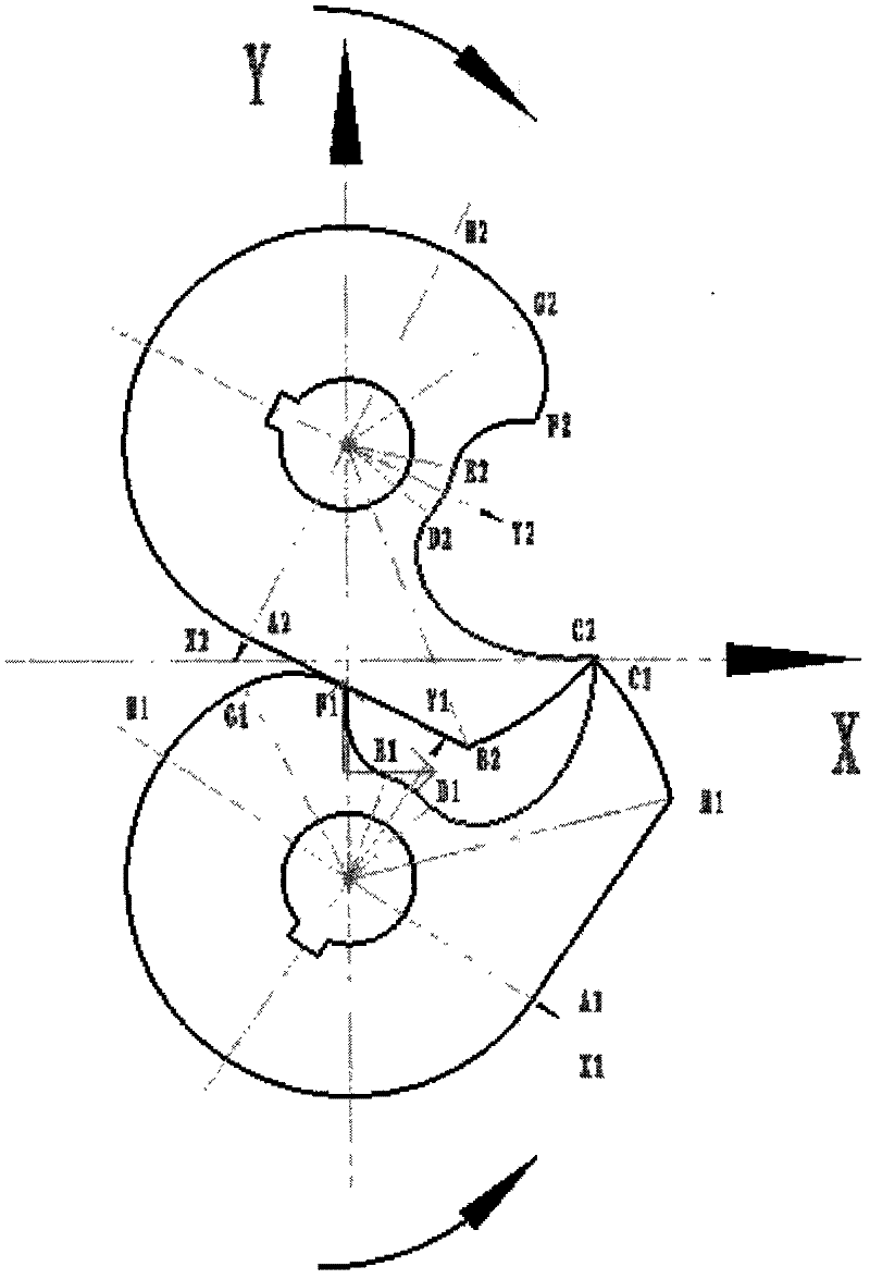
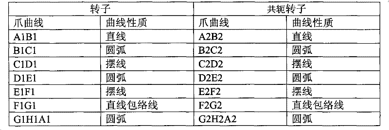
[0061] Such as Figure 1-2 As shown, a schematic diagram of the appearance of the rotor and the conjugate rotor formed by a seven-segment straight-claw rotor design method described in the embodiment of the present invention. The rotor formed by the seven-segment straight claw rotor design method described in the embodiment of the present invention includes the following curve segments: A1B1, B1C1, C1D1, D1E1, E1F1, E1G1, G1H1A1, connecting the above curves to form the outer shape curve of the rotor, The generation mechanism of each segment of the curve:

[0062] A1B1 is produced by F2G2 conjugation on the conjugated rotor;

[0063] B1C1 is a circular arc, which is produced by the conjugate of D2E2 on the conjugated rotor;

[0064] C1D1 is a cycloid, which is generated by the conjugate point C2 on the conjugated rotor;

[0065] D1E1 is a circular arc, which is produced by the conjugate of B2C2 on the conjugated rotor;

[0066] E1F1 is a section of cycloid, which is produce...


PUM


Abstract

The invention relates to a design method of a seven-segment type straight claw rotor. The rotor formed by using the design method comprises the following curved segments A1B1, B1C1, C1D1, D1E1, E1F1, E1G1 and G1H1A1, and all the curves are connected to form a shape curve of the rotor, wherein the production mechanism of each segment of curve is as follows: A1B1 is generated by conjugation of F2G2on a conjugated rotor; B1C1 is a segment of arc and is generated by conjugation of D2E2 on the conjugated rotor; C1D1 is a segment of cycloid curve and is generated by conjugation of a C2 point on the conjugated rotor; D1E1 is a segment of arc and is generated by conjugation of B2C2 on the conjugated rotor; E1F1 is a segment of cycloid curve and is generated by conjugation of a B2 point on the conjugated rotor; E1G1 is a segment of straight line envelop curve and is generated by conjugation of A2B2 on the conjugated rotor; and G1H1A1 is segment of arc and is generated by conjugation of G2H2A2on the conjugated rotor. The design method of the seven-segment type straight claw rotor has the beneficial effects that the seven-segment type straight claw rotor can be machined by numerical control machines and can be used for mass production.

Description

technical field [0001] The invention relates to a rotor for an oil-free compressor and an oil-free vacuum pump, in particular to a design method for a seven-section straight claw rotor. Background technique [0002] The claw device applied to vacuum pumps or compressors generally includes: two shafts, one driving shaft drives the driven shaft to rotate synchronously and reversely through a pair of synchronous gears. One or more groups of rotors are installed on the two shafts, two mutually meshing definition rotors and conjugate rotors. The two rotors are meshed and rotated to provide a periodic cycle of intake and exhaust compression movements, thereby completing the vacuuming of the gas and the compression of the gas. The rotors described in the prior art are generally screw-type or crank-claw type, but the precision of the screw-type rotor is too high, and the processing of existing equipment cannot meet the precision requirements, while the crank-claw rotor can only be ...

Claims


Application Information

Patent Timeline
Patent Type & Authority Applications(China)
IPC IPC(8): G06F17/50
Inventor 王连智
Owner 王连智
Learn More