Three level power converting device

A power converter and power conversion technology, which is applied to output power conversion devices, electrical components, and AC power input to DC power output, etc., can solve problems such as size increase, device price increase, and significant problems.

Inactive Publication Date: 2012-02-08
FUJI ELECTRIC CO LTD
View PDF6 Cites 3 Cited by
  • Summary
  • Abstract
  • Description
  • Claims
  • Application Information

AI Technical Summary

Problems solved by technology

[0023] In general, by making the main circuit conductors of the DC part into a parallel plate structure (laminated structure), any generated magnetic field is eliminated and a reduction in wiring inductance is achieved, but in such Image 6 When the fuse is connected like in the system, the parallel plate structure cannot be used in this part, so that the reduction of the wiring inductance cannot be realized.
[0024] Moreover, due to Figure 15 Fuses are also used in two places in the structure shown, so the wiring inductance increases in the same way
[0025] When connecting a fuse as described above, a high surge voltage is generated at the time of switching due to an increase in inductance, so it is necessary to use a module with a high withstand voltage, connect a snubber circuit, etc., resulting in a problem of size increase and device price increase
Especially in the case of a three-level inverter, since fuses need to be connected at two locations, the problem is significant
[0026] Moreover, in Figure 16 In the circuit structure shown, no protection can be performed for two-level operation

Method used


Image

  • Three level power converting device
  • Three level power converting device
  • Three level power converting device

Examples


Embodiment 1

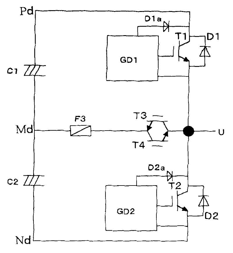
[0053] figure 1 A first embodiment of the invention is shown in . It is a circuit configuration of a voltage-type three-level power converter having a DC power supply, a first IGBT T1, a second IGBT T2, and a bidirectional switching element as one phase, and the DC power supply is configured with two capacitors C1 and C2 connected in series As a DC power supply, and has a positive pole, an intermediate electrode, and a negative pole; the collector of the first IGBT T1 is connected to the positive pole of the DC power supply, and the first IGBT T1 is connected in antiparallel to the diode D1; the emitter of the second IGBT T2 connected to the negative pole of the DC power supply, and the second IGBT T2 is connected in antiparallel with the diode; The connection point of the emitter of the first IGBT T1 and the collector of the second IGBT T2 is connected to the intermediate electrode of the DC power supply. Although a single-phase circuit is shown in the figure, a single-pha...

Embodiment 2

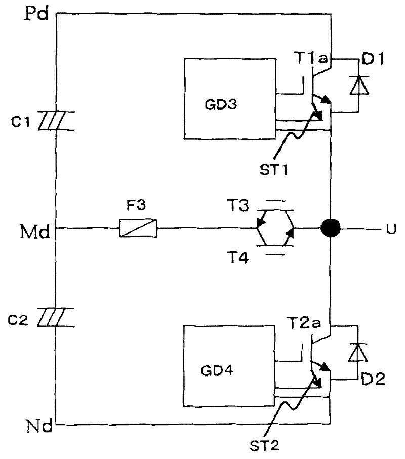
[0058] figure 2 A second embodiment of the present invention is shown. The difference from the first embodiment is that IGBTs with current sensing terminals for detecting current are used as IGBTs T1a and T2a, and the overcurrent shutoff unit detects overcurrent using the current sensing terminals and cuts off the gate signal. Since this overcurrent protection method is known from JP-A-4-79758 and the like, a detailed description is omitted. For this structure, the protection of each overcurrent path can also be realized in the same manner as in the first embodiment.

Embodiment 3

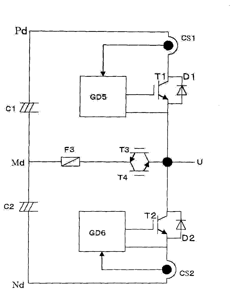
[0060] image 3 A third embodiment of the present invention is shown. The point of difference from the first and second embodiments is that current detectors CS1 and CS2 such as Hall CTs are used for overcurrent detection. When an overcurrent is detected, the ON signal of the gate drive circuit is cut off. For this structure, the protection of each overcurrent path can also be realized in the same manner as in the first and second embodiments.


PUM


Abstract

Aspects of the invention are directed to a three-level power converter that has, as one phase, a bidirectional switching element connected to the series connection point of a series circuit of a first insulated gate bi-polar transistor ("IGBT") and second IGBT and an intermediate electrode of a direct current power supply. Also included is a fuse connected between the bidirectional switching element and the intermediate electrode of the direct current power supply, and an overcurrent shutdown unit provided in each gate drive circuit of the first and second IGBTs, are provided as protection from a power supply short circuit phenomenon occurring in the event of a short circuit failure of any of the IGBTs or diodes.

Description

technical field [0001] The invention relates to an arm short-circuit protection method of a three-level inverter or converter. Background technique [0002] JP-A-2004-248479( Figure 1~3 ) shows a protection circuit using fuses in a three-level converter. The three-level converter circuit shown here is a structure having a circuit as one phase in which a capacitor as a DC power supply is connected in series, a positive electrode, an intermediate electrode, and a negative electrode are used as DC terminals, and a diode is connected between the positive electrode and the negative electrode. A series connection circuit of four IGBTs (two on the upper arm and two on the lower arm) connected in antiparallel, between the series connection point of the two upper arm IGBTs and the middle electrode of the DC power supply, and in the series connection of the two lower arm IGBTs A diode for clamping the middle electrode is connected between the connection point and the middle electrod...

Claims


Application Information

Patent Timeline
Patent Type & Authority Applications(China)
IPC IPC(8): H02M1/32H02H7/10
CPCH02M1/32H02M7/487H03K17/08148H03K17/0828
Inventor 泷泽聪毅
Owner FUJI ELECTRIC CO LTD
Why Eureka
Try Eureka