Method of soldering electronic component, and apparatus of same

An electronic component and welding method technology, which is applied in the field of electronic component welding and welding device, can solve the problems of time-consuming welding process, inability to control the amount of solder, etc., and achieve the effect of solving the residual solder

Inactive Publication Date: 2014-05-28
MURATA MFG CO LTD
View PDF6 Cites 0 Cited by
  • Summary
  • Abstract
  • Description
  • Claims
  • Application Information

AI Technical Summary

Problems solved by technology

In this way, since the bobbin is pulled up in the Z direction every time it is dipped, it is possible to make more than the required amount of liquid solder adhere to the electrodes, and it is impossible to control the amount of solder
In addition, the welding process is quite time-consuming because the action of raising and lowering the bobbin must be repeated twice

Method used


Image

  • Method of soldering electronic component, and apparatus of same
  • Method of soldering electronic component, and apparatus of same
  • Method of soldering electronic component, and apparatus of same

Examples


Embodiment Construction

[0041] Hereinafter, preferred embodiments of the present invention will be described based on the drawings.

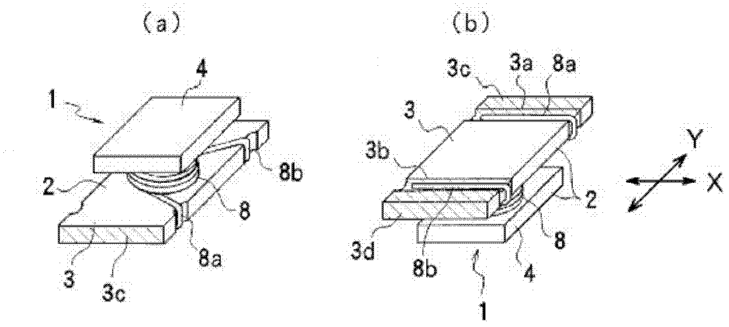
[0042] figure 1 A chip coil is shown as an example of the electronic component of the present invention. This chip coil 1 is formed by winding a coil 8 around a winding portion (not shown) of a magnetic core 2 , and the magnetic core 2 has flange portions 3 and 4 at both ends thereof. Both ends 8a, 8b of the coil 8 are drawn to the back side of the first flange portion 3 and drawn into two groove portions 3a, 3b formed at both ends of the back face of the flange portion 3 . Continuous electrodes 3c, 3d (indicated by oblique lines) are formed in the region from the bottom surface of these groove portions 3a, 3b to both end surfaces of the flange portion 3 . These electrodes 3c, 3d are welded to both ends 8a, 8b of the coil 8, respectively, as described below. exist figure 1 Here, the direction perpendicular to the mutual facing direction of the pair of electrodes ...


PUM


Abstract

A method of soldering an electronic component, which is free of leftover solder existing between electrodes and allows a suitable amount of liquid solder to stick to the electrodes. A chip coil (1) is supported above the liquid solder surface so that the direction in which the pair of electrodes face each other is parallel to the liquid solder surface, and is swung about a first axis (X1), which is positioned below the liquid solder surface, as a center of rotation so that the left and right electrodes (3c, 3d) are alternately dipped into the liquid solder surface. Next, after horizontally holding the chip coil above the liquid solder surface and in a state in which the liquid solder is connected to the electrode through surface tension, the chip coil is rotated upward about a second axis (Y1) as a center of rotation, and liquid solder is shaken off from the electrodes. As liquid solder does not contact the region between the electrodes during dipping and pull-up, leftover solder does not appear between the electrodes.

Description

technical field [0001] The invention relates to a method and a device for adhering liquid solder to electrodes of electronic components such as chip coils. Background technique [0002] When manufacturing a chip coil, after winding the coil on the bobbin, the both ends of the coil are pulled to the electrodes formed on the back of one of the flanges (first flange) of the bobbin, and then the electrodes and the coil are welded. Ends. The soldering method is to dip the back surface of the first flange part of the bobbin forming the electrode into liquid solder and pull up the bobbin so that the liquid solder adheres to the electrode. However, simply pulling up the back surface of the first flange portion of the bobbin by immersing it in liquid solder causes a problem that solder adheres to parts other than the electrodes or a more than necessary amount of solder adheres. [0003] Patent Document 1 discloses a method of attaching liquid solder to electrodes of a chip coil. S...

Claims


Application Information

Patent Timeline
Patent Type & Authority Patents(China)
IPC IPC(8): H01F41/10B23K1/00B23K1/08B23K3/00
CPCB23K3/0684H01F41/10H01F17/045H01F27/292B23K1/08
Inventor 桧垣忠则及川孝富泽洋介
Owner MURATA MFG CO LTD
Why Eureka
Try Eureka