Screw locking machine

A locking machine and locking mechanism technology, applied in metal processing, metal processing equipment, manufacturing tools, etc., can solve the problems of reduced processing efficiency, damage to locked products, and excessive size, so as to improve processing efficiency and accuracy and convenience, reduce damage rate effect

Inactive Publication Date: 2012-02-15
HUIZHOU TCL MOBILE COMM CO LTD
View PDF11 Cites 17 Cited by
  • Summary
  • Abstract
  • Description
  • Claims
  • Application Information

AI Technical Summary

Problems solved by technology

But the locking machine is equipped with a variety of torque-limiting mechanisms, and it is difficult to grasp the firmness of the screw tightening. If the force is small, it will easily fall off, and if the force is large, it will easily damage the workpiece.
[0003] However, when the sliding table of the locking machine slides downward, if the control is not accurate, the sliding table will go down too fast and too large, which will easily cause damage to the workpiece.
And in the process of tightening the screws, the electric bit is easy to scratch the shell of the workpiece, and the screw sucked by the electric bit cannot be connected with the screw hole on the workpiece, which will cause uneven force on the screw hole of the workpiece and lead to slippage, reducing the processing time. efficiency
[0004] And the locking machine in the prior art cannot realize the continuous supply of screws during work, or because the structure of the supply screw is relatively simple, the supply of screws is not timely, it is easy to cause the locking machine to have no screw locking, which reduces the processing efficiency and product quality. quality
The screwdriver head of the locking machine has a limited range of movement and inaccurate positioning, which is easy to cause damage to the locking product
There is only a fixed station under the screw bit. After the processing is completed, the product to be locked needs to be replaced, which reduces the processing efficiency and brings a lot of inconvenience to the user.

Method used


Image

  • Screw locking machine
  • Screw locking machine
  • Screw locking machine

Examples


Embodiment Construction

[0023] The present invention provides a screw locking machine. In order to make the purpose, technical solution and advantages of the present invention clearer and clearer, the present invention will be further described in detail below with reference to the accompanying drawings and embodiments.

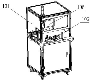
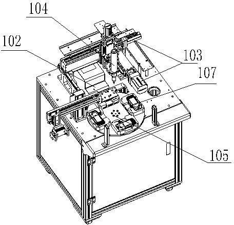
[0024] The invention provides a screw locking machine, through the cooperation and linkage of the feeding mechanism, the three-axis positioning mechanism, the locking mechanism and the product positioning mechanism, the products with locking can be processed continuously, and the processing efficiency of the screw locking machine is improved. The damage rate of products to be locked and paid is reduced. Such as figure 1 and image 3 The screw locking machine shown comprises a frame 101 which may take any technical form known in the art. The frame 101 is provided with a feeding mechanism 102, a three-axis positioning mechanism 103, a locking mechanism 104 and a product positioning ...


PUM


Abstract

The invention discloses a screw locking machine which comprises a machine frame, wherein a feeding mechanism, a three-shaft positioning mechanism, a locking mechanism and a product positioning mechanism are arranged on the machine frame. The screw locking machine provided by the invention can realize the continuous operation of the screw locking machine. The locking mechanism can position any point of the three-shaft positioning mechanism, thereby improving the accuracy and convenience of a locking process. Especially, the locking mechanism prevents a sliding table from generating a huge impact force during an automatic descending process, thereby avoiding scratching a machined part or damaging the threaded hole of the machined part, promoting the processing efficiency of the screw locking machine and reducing the damage rate of a to-be-locked product.

Description

technical field [0001] The invention relates to a screw locking machine. Background technique [0002] When assembling the screws on the product, the traditional manual tightening method is generally adopted, which wastes a lot of manpower and material resources, and the work efficiency is low. Later, with the rapid development of science and technology, locking tools such as electric screw machines and pneumatic screw machines gradually appeared, replacing the manual tightening method, improving work efficiency and reducing the work intensity of workers locking screws. However, the locking machine is equipped with various torque-limiting mechanisms, and it is difficult to grasp the firmness of screw tightening. If the force is small, it will easily fall off, and if the force is large, it will easily damage the workpiece. [0003] When the sliding table of the locking machine slides downward, if the control is not accurate, the sliding table will go down too fast and too la...

Claims


Application Information

Patent Timeline
Patent Type & Authority Applications(China)
IPC IPC(8): B23P19/12
Inventor 聂大华李建强温永涛
Owner HUIZHOU TCL MOBILE COMM CO LTD
Why Eureka
Try Eureka