Automatic charging and discharging device of die cutting machine

An automatic loading and unloading and die-cutting machine technology, which is applied in the direction of conveyor objects, transportation and packaging, etc., can solve problems such as high risk, and achieve the effect of guaranteeing work safety and improving work efficiency

Active Publication Date: 2012-02-15
南通哥班玻璃纤维制品有限公司
View PDF7 Cites 13 Cited by
  • Summary
  • Abstract
  • Description
  • Claims
  • Application Information

AI Technical Summary

Problems solved by technology

[0003] Aiming at the deficiencies of the above-mentioned prior art, the present invention provides an automatic loading and unloading device for a die-cutting machine, which mainly solves the problem of high risk during loading and unloading of die-cutting, so that the efficiency of carton production can be guaranteed, and the Avoid personal injury due to improper operation during production

Method used


Image

  • Automatic charging and discharging device of die cutting machine
  • Automatic charging and discharging device of die cutting machine

Examples


Embodiment Construction

[0010] Specific implementation examples

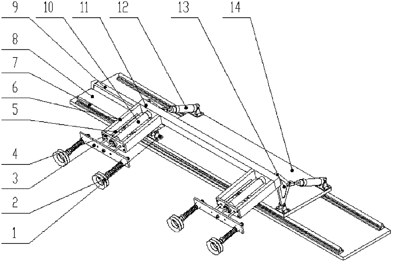
[0011] The present invention will be further described below in conjunction with the accompanying drawings.

[0012] An automatic loading and unloading device for a die-cutting machine, including a twist support 1, a suction cup 2, a suction cup bottom plate 3, a cylinder top plate 4, a guide rod 5, a cylinder support block 6, a cylindrical guide rail 7, a guide rail bottom plate 8, an SU cylinder 9, small Cylinder 10, small cylinder bottom plate 11, rotary cylinder 12, connecting block 13, big moving plate 14, such as figure 1 As shown, wherein, the cylindrical guide rail 7 is symmetrically installed on both sides of the guide rail bottom plate 8; the large moving plate 14 is installed above the cylindrical guide rail 7; the SU cylinder 9 is installed on the upper side of the guide rail bottom plate 8 , the underside of the large movable plate 14; a pair of twisted supports 1 are symmetrically installed on one side of the large movab...


PUM


Abstract

The invention discloses an automatic charging and discharging device of a die cutting machine, which effectively realizes the automatic charging and discharging of the die cutting machine, needs no manpower, greatly improves work efficiency and guarantees work safety. The automatic charging and discharging device of the die cutting machine consists of twisting supports, a sucker, a sucker baseplate, a cylinder top plate, a guide rod, cylinder supporting blocks, cylindrical guide rails, a guide rail baseplate, an SU cylinder, a small cylinder, a small cylinder baseplate, rotating cylinders, connecting blocks and a large movable plate, wherein the cylindrical guide rails are symmetrically arranged on two sides of the guide rail baseplate; the large movable plate is arranged above the cylindrical guide rails; the SU cylinder is arranged on an upper side of the guide rail baseplate and on a lower side of the large movable plate; a pair of twisting supports are symmetrically arranged on one side of the large movable plate, and a pair of rotating cylinders are symmetrically arranged on the other side of the large movable plate; the connecting blocks are arranged on the twisting supports; the rotating cylinder is connected with the connecting blocks on the same side; the small cylinder baseplate is fixed on the connecting blocks; the small cylinder is arranged on the small cylinder baseplate; the cylinder supporting blocks are arranged on two sides of the small cylinder.

Description

technical field [0001] The invention relates to a device based on the principle of negative pressure, in particular to an automatic loading and unloading device of a die-cutting machine, which uses the work of a cylinder to realize the function of feeding and unloading cardboard. Background technique [0002] A die-cutting machine is a device that shapes cardboard by pressure. Existing die-cutting machines can only rely on manpower for loading and unloading. If they work for a long time, they are prone to fatigue. At the same time, the die-cutting machine runs very fast, so it is easy to cause personal injury. So there is an urgent need for a machine to replace manpower for this dangerous work. Contents of the invention [0003] Aiming at the deficiencies of the above-mentioned prior art, the present invention provides an automatic loading and unloading device for a die-cutting machine, which mainly solves the problem of high risk during loading and unloading of a die-cut...

Claims


Application Information

Patent Timeline
Patent Type & Authority Applications(China)
IPC IPC(8): B65G47/91
Inventor 于复生沈孝芹张涵李德利李波孙耀
Owner 南通哥班玻璃纤维制品有限公司
Why Eureka
Try Eureka