Automatically loaded carriage

An automatic loading and unloading, carriage technology, applied in the direction of vehicles with elevated loading platforms, vehicles with chain/ring belts, etc. problems, etc., to reduce the use of labor, reduce loading and unloading time, and improve efficiency

Inactive Publication Date: 2014-02-12
王延斌
View PDF8 Cites 14 Cited by
  • Summary
  • Abstract
  • Description
  • Claims
  • Application Information

AI Technical Summary

Problems solved by technology

However, its shortcomings are: 1. It only solves the unloading process, and does not solve the problem of loading; 2. The goods stacked in the compartment cannot be automatically exported to the unloading device for unloading, or manual or other devices are required to unload.
However, its shortcomings are: 1. When the goods are loaded into the compartment, the automatic layering of the goods cannot be realized, and a lot of manpower is needed; The weight has to be reconsidered

Method used


Image

  • Automatically loaded carriage
  • Automatically loaded carriage
  • Automatically loaded carriage

Examples


Embodiment 1

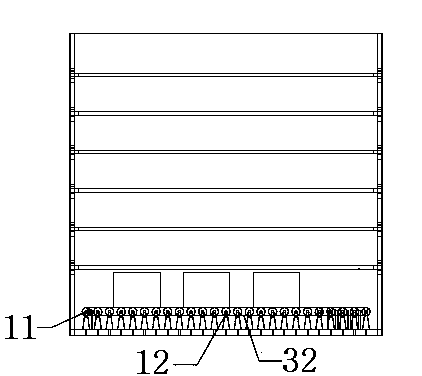
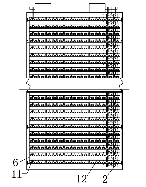
[0034] The bottom of the compartment is arranged with longitudinal and transverse rollers with brackets, and the brackets are connected with the bottom of the compartment by bolts. Horizontal rolling rollers are arranged every 200mm along the longitudinal direction, and a row is arranged every 100mm along the horizontal direction; the longitudinal rolling rollers are arranged on one side of the carriage, interlaced with the horizontal rolling rollers, one every 200mm along the longitudinal direction, and one row is every 100mm along the horizontal direction, a total of 5 rows, of which The three rows in the middle are connected to the motor by chains, and the two rows on the far side are not connected to the motor by chains. The lifting rack 6 is laid on the bottom of the compartment for a six-layer structure frame, and the whole structure frame is stored in the gap between the vertical and horizontal rollers.

Embodiment 2

[0036] 1. When loading the goods into the compartment:

[0037]1.1 Start the longitudinal motor 92, drive the longitudinal roller 2 through the longitudinal transmission belt 31 to make it rotate longitudinally, put the goods one by one on the longitudinal roller, and the goods will slowly flow into the compartment as the roller rolls. When a row has been filled longitudinally, the transverse motor 91 is started. The transverse motor 91 drives the bevel gear 5 to rotate through the chain 4, the chain 4 is guided through the chain guide wheel 101 at the bottom of the box, the bevel gear 5 meshes with the transverse drive wheel 11 with the bevel gear, and the transverse drive wheel with the bevel gear 11 produces lateral rolling, which drives the lateral driven roller 12 to roll through the lateral transmission belt 32, so that the goods are laterally moved to one side. Reciprocating like this always waits for the goods to cover one deck of the compartment, and stops the transv...


PUM


Abstract

The invention provides an automatically loaded carriage, which is characterized by comprising a horizontal driving wheel, a horizontal driven wheel, a longitudinal idler wheel, a longitudinal driving belt, a horizontal driving belt, a driving chain, a conical gear, a lifting goods shelf, a rope, a fastening lock, a horizontal motor, a longitudinal motor, a rope motor, a chain guide wheel, a belt guide wheel and a guide groove, wherein the horizontal motor, the longitudinal motor and the rope motor are arranged at the end of the carriage, the horizontal motor drives the conical gear to rotate through the chain, the chain is guided by the chain guide wheel arranged at a box bottom, the conical gear is meshed with the horizontal driving wheel provided with conical gears, and the horizontal driving wheel is connected with a horizontal driven idler wheel through the horizontal driving belt. The device can be matched with a warehouse conveying goods crawler belt for realizing automatically loading goods into a warehouse and unloading the goods from the warehouse; the carriage is more applicable to fragile articles fear of heavy loading, and the carriage structure enables the goods to be placed in a layered manner and to be prevented from being pressed, so that the carriage is particularly suitable for the express industry.

Description

technical field [0001] The invention relates to a loading and unloading carriage, in particular to an automatic loading and unloading carriage, and belongs to the technical field. Background technique [0002] Most of the compartments or containers that exist on the market rely on labor or forklifts to load goods into the compartments or containers. Such loading and unloading methods are inefficient, labor-intensive and time-consuming. And for some fragile and heavy-duty goods, they cannot be well protected. Now the market uses high-cost packaging, or uses modified carriages with lifting shelves to transport fragile and heavy-duty goods. Based on this, I have worked out a kind of novel structure compartment, can overcome above deficiency. [0003] Chinese Patent Application No. 200410023962.5, published on January 26, 2005, the invention is called the unloading device for bulk cargo in containers. The top hinge shaft worn on the upper end of the upper link is supported on...

Claims


Application Information

Patent Timeline
Patent Type & Authority Applications(China)
IPC IPC(8): B60P1/36B60P1/44
Inventor 王延斌
Owner 王延斌
Why Eureka
Try Eureka