Air conditioner for machine room

A technology for air conditioners and computer rooms, applied in air conditioning systems, applications, refrigerators, etc., can solve problems such as equipment condensation, difficulty in judging whether the air quality meets the requirements, corrosion, etc., and achieve the effect of avoiding condensation and air quality problems

Inactive Publication Date: 2012-02-15
GUANGDONG MIDEA ELECTRIC APPLIANCES CO LTD
View PDF4 Cites 6 Cited by
  • Summary
  • Abstract
  • Description
  • Claims
  • Application Information

AI Technical Summary

Problems solved by technology

Among them, the ethylene glycol natural cooling system needs to add a set of ethylene glycol heat exchange coils, which increases the load of the indoor fan, and the energy consumption of the fan increases throughout the year, offsetting part of the energy-saving effect; the main disadvantage of directly introducing fresh air is that when the outdoor When the temperature is too low, the introduction will cause condensation on the equipment. In addition, the fresh air must be filtered. The filter requires regular maintenance by professionals, and it is difficult to determine whether the quality of the filtered air meets the requirements, and it may corrode the equipment in the computer room.

Method used


Image

  • Air conditioner for machine room
  • Air conditioner for machine room
  • Air conditioner for machine room

Examples


Embodiment 1

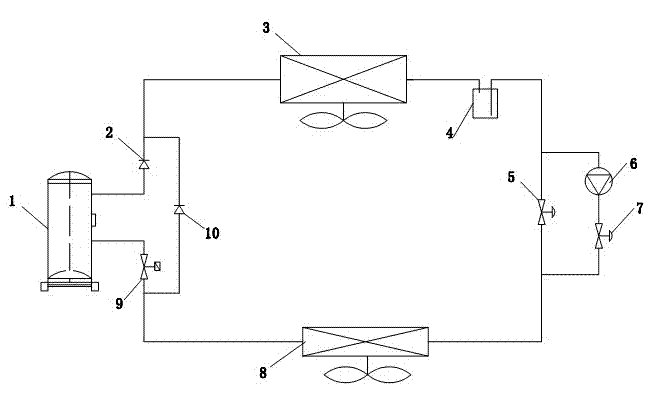
[0013] Such as figure 1 As shown, the air conditioner used in the machine room of the present invention includes a compressor 1, a first one-way control valve 2, a condenser 3, a liquid reservoir 4, a first throttling device 5, an evaporator 8, and an on-off control valve 9. Liquid pump 6, second throttling device 7 and second one-way control valve 10, wherein the outlet of compressor 1 is connected to the inlet of condenser 3 through the first one-way control valve 2, and the outlet of condenser 3 is connected to The inlet of the liquid reservoir 4, the outlet of the liquid reservoir 4 is connected to the inlet of the evaporator 8 through the first throttling device 5, the outlet of the evaporator 8 is connected to the inlet of the on-off control valve 9, and the outlet of the on-off control valve 9 Connected to the inlet of the compressor 1, the liquid pump 6 is connected in series with the second throttling device 7 and connected to both ends of the first throttling device ...

Embodiment 2

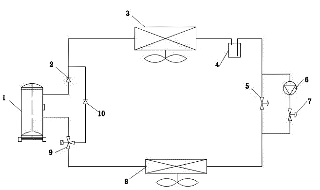
[0017] The difference between this embodiment and embodiment 1 is: as figure 2 As shown, the on-off control valve 9 is a three-way on-off control valve, the inlet of the three-way on-off control valve is connected to the outlet of the evaporator 8, one outlet is connected to the inlet of the compressor 1, and the other outlet is connected to the second one-way control valve 10. Entrance. In the energy-saving operation mode of this embodiment, the refrigerant is powered by the liquid pump 6, throttled by the second throttling device 7, evaporates in the evaporator 8, and then passes through the three-way on-off control valve 9 and the second one-way control valve in sequence. 10 to the condenser 3 to condense, and then return to the liquid pump 6 after passing through the liquid reservoir 4, so that the energy-saving mode refrigeration can be realized in such a cycle. Other structures and working principles are the same as in Embodiment 1.


PUM


Abstract

The invention relates to an air conditioner for a machine room, wherein an outlet of a compressor is connected to an inlet of a condenser through a first unidirectional control valve, an outlet of the condenser is connected to an inlet of a liquid-storing device, an outlet of the liquid-storing device is connected to an inlet of an evaporator through a first throttling device, an outlet of the evaporator is connected to an inlet of an on-off control valve, and an outlet of the on-off control valve is connected to an inlet of the compressor. The air conditioner for the machine room is characterized by also comprising a liquid pump, a second throttling device and a second unidirectional control valve, wherein the liquid pump is connected in parallel to both ends of the first throttling device after being connected in series with the second throttling device, an inlet of the liquid pump is connected with the outlet of the liquid-storing device, an outlet of the liquid pump is connected with an inlet of the second throttling device, an outlet of the second throttling device is connected with the inlet of the evaporator, an inlet of the second unidirectional control valve is connected onto a pipeline between the evaporator and the on-off control valve, and an outlet of the second unidirectional control valve is connected onto a pipeline between the first unidirectional control valve and the condenser. The air conditioner for the machine room has an obvious energy-saving effect, the load of a fan is not increased, and fresh-wind condensation and air-quality problems are avoided.

Description

technical field [0001] The invention is an air conditioner used in a computer room, which belongs to the improvement technology of the air conditioner used in a computer room. Background technique [0002] With the development of the information industry, the number of communication computer rooms is also increasing rapidly. To maintain the normal operation of the computer room, refrigeration equipment must be provided to maintain the environmental requirements of the computer room. According to existing statistics, the cooling energy consumption of the computer room accounts for nearly 100% of the entire computer room system. 40% of the energy consumption, the cooling and energy saving of the computer room is becoming more and more important. Among the existing energy-saving technologies for machine room cooling, the cooling capacity of the outdoor environment is used to achieve cooling: natural cooling of ethylene glycol and direct introduction of fresh air. Among them, t...

Claims


Application Information

Patent Timeline
Patent Type & Authority Applications(China)
IPC IPC(8): F24F1/00F25B41/00F25B41/06
Inventor 王坚雷海涛黄德勇
Owner GUANGDONG MIDEA ELECTRIC APPLIANCES CO LTD
Why Eureka
Try Eureka