
Electronic kiln feed mechanism

A kiln and electronic technology, applied in the direction of furnace, furnace components, charge control, etc., can solve the problems of intermittent feeding and discharging, inability to sinter high-end products, waste of kiln, etc.

Inactive Publication Date: 2012-02-15
SUZHOU HUIKE EQUIP CO LTD
View PDF4 Cites 7 Cited by
  • Summary
  • Abstract
  • Description
  • Claims
  • Application Information

AI Technical Summary

Problems solved by technology

The feeding mechanism of this structure has the disadvantage of slow feeding speed, which is not enough to make full use of the efficiency of the kiln and wastes energy in the kiln, because the time spent from waiting for one setter to entering the previous setter is about If it is more than 1-2min, there will be interruptions in the feeding and discharging of the furnace, which will affect the process performance of the product and make it impossible to sinter high-end products.

Method used


Image

  • Electronic kiln feed mechanism
  • Electronic kiln feed mechanism
  • Electronic kiln feed mechanism

Examples


Embodiment Construction

[0019] In order to enable the examiners of the patent office, especially the public, to understand the technical essence and beneficial effects of the present invention more clearly, the applicant will describe in detail the following in the form of examples, but none of the descriptions to the examples is an explanation of the solutions of the present invention. Any equivalent transformation made according to the concept of the present invention which is merely formal but not substantive shall be regarded as the scope of the technical solution of the present invention.

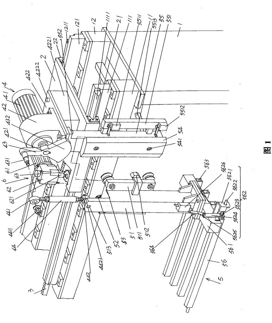
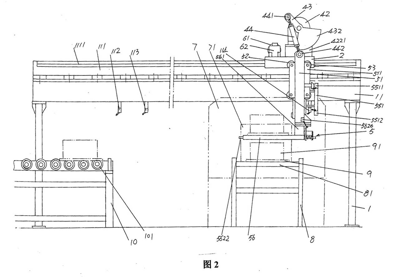
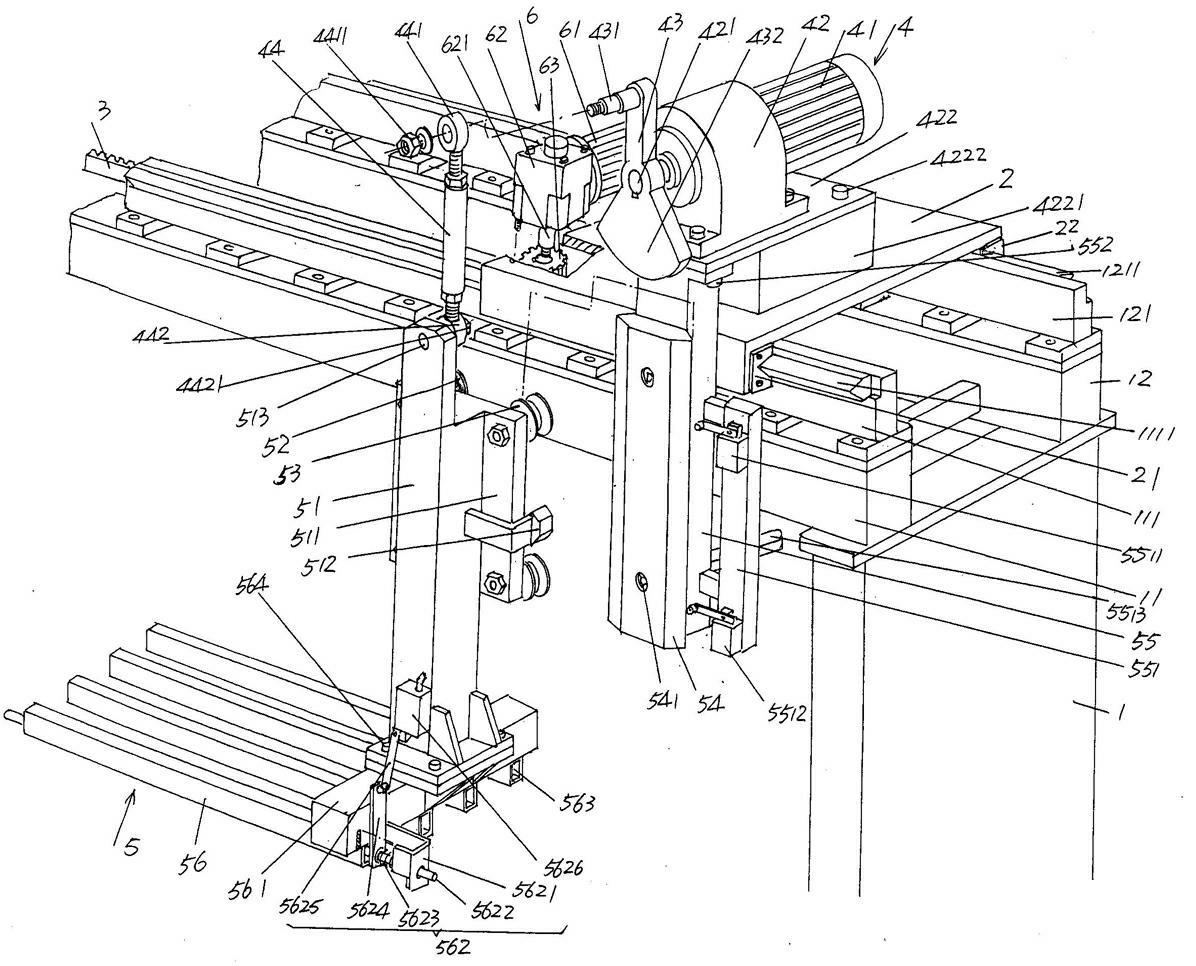
[0020] See figure 1 , provides a frame 1, and this frame 1 corresponds to the side of the furnace mouth of the electronic kiln in the state of use, and the electronic kiln feeding mechanism of the present invention can be an electronic kiln feeding , it is also possible to load multiple electronic kilns. When loading multiple electronic kilns, the length of rack 1 should meet the interval of each electro...


PUM


Abstract

The invention relates to an electronic kiln feed mechanism, and belongs to the technical field of electronic product sintering kilns. The feed mechanism comprises a chassis, a sliding stand, a rack, a power driven gear, a feeding device and a sliding stand shifter, wherein the top of the chassis is fixedly provided with a first beam and a second beam, a first guide rail base is fixedly arranged on the first beam, the first guide rail base is fixedly provided with a first guide rail, the second beam is fixedly provided with a second guide rail base, and a second guide rail is fixedly arranged on the second guide rail base; the sliding stand is slidably matched with the first guide rail, and is slidably matched with the second guide rail; the rack is fixed on one side, facing to the second guide rail base, on the first guide rail base or one side, facing to the first guide rail base, on the second guide rail base; the power driven gear is arranged on the sliding stand; the feeding device is connected with the power driven gear; and the sliding stand shifter is arranged on the sliding stand and is matched with the rack. The feed mechanism provided by the invention has the advantages that the firing efficiency of an electronic product in unit time of an electronic kiln is improved and energy sources are saved for the electronic kiln.

Description

technical field [0001] The invention belongs to the technical field of sintering kilns for electronic products, and in particular relates to a feeding mechanism for electronic kilns, which is used for transporting electronic products to be sintered to an entrance corresponding to a hearth of the electronic kiln. Background technique [0002] Electronic furnaces are mainly used for sintering such as ferrite, ceramic inductor substrate, ceramic capacitor dielectric substrate, lithium iron phosphate powder, powder for various electronic products, etc. [0003] As known in the industry, electronic kilns are equipped with a feeding mechanism, which is used to transport the products to be sintered (also called firing) to the furnace mouth, that is, to the furnace mouth for feeding The area is pushed into the furnace one by one by the pushing mechanism. This kind of feeding mechanism must wait for the previous setter plate (the electronic product to be fired on the setter plate) t...

Claims


Application Information

Patent Timeline
Patent Type & Authority Applications(China)
IPC IPC(8): F27D3/00
Inventor 杨国栋
Owner SUZHOU HUIKE EQUIP CO LTD
Learn More