Tunnel kiln structure for sintering electronic products

A technology of electronic products and tunnel kiln, which is applied in the field of tunnel kiln structure for sintering electronic products, which can solve the problems of low firing efficiency, glue dripping in chimneys, and high labor intensity of workers, so as to save energy, reduce labor intensity, and improve firing efficiency effect

Active Publication Date: 2011-11-02
江苏博涛智能热工股份有限公司
View PDF7 Cites 2 Cited by
  • Summary
  • Abstract
  • Description
  • Claims
  • Application Information

AI Technical Summary

Problems solved by technology

However, there are the following technical problems in firing the above-mentioned electronic products or powder materials for electronic products in a chamber furnace: one is that the firing efficiency is low, and it is difficult to meet the requirements of industrial scale-up production; The aforementioned cleaning of the box furnace is required by workers; third, it is not conducive to energy saving, because when cleaning the box furnace, it needs to be cooled to normal temperature in advance
Yet so far in published patents and non-patent literature, there is no technical inspiration to improve the tunnel kiln so as to avoid chimney dripping

Method used


Image

  • Tunnel kiln structure for sintering electronic products
  • Tunnel kiln structure for sintering electronic products
  • Tunnel kiln structure for sintering electronic products

Examples


Embodiment Construction

[0021] In order to enable the examiners of the patent office, especially the public, to understand the technical essence and beneficial effects of the present invention more clearly, the applicant will describe in detail the following in the form of examples, but none of the descriptions to the examples is an explanation of the solutions of the present invention. Any equivalent transformation made according to the concept of the present invention which is merely formal but not substantive shall be regarded as the scope of the technical solution of the present invention.

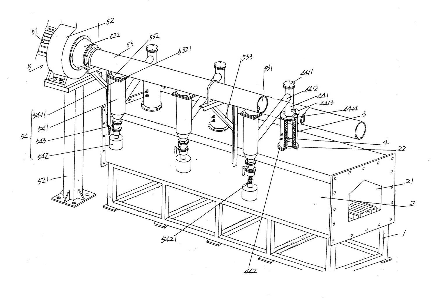
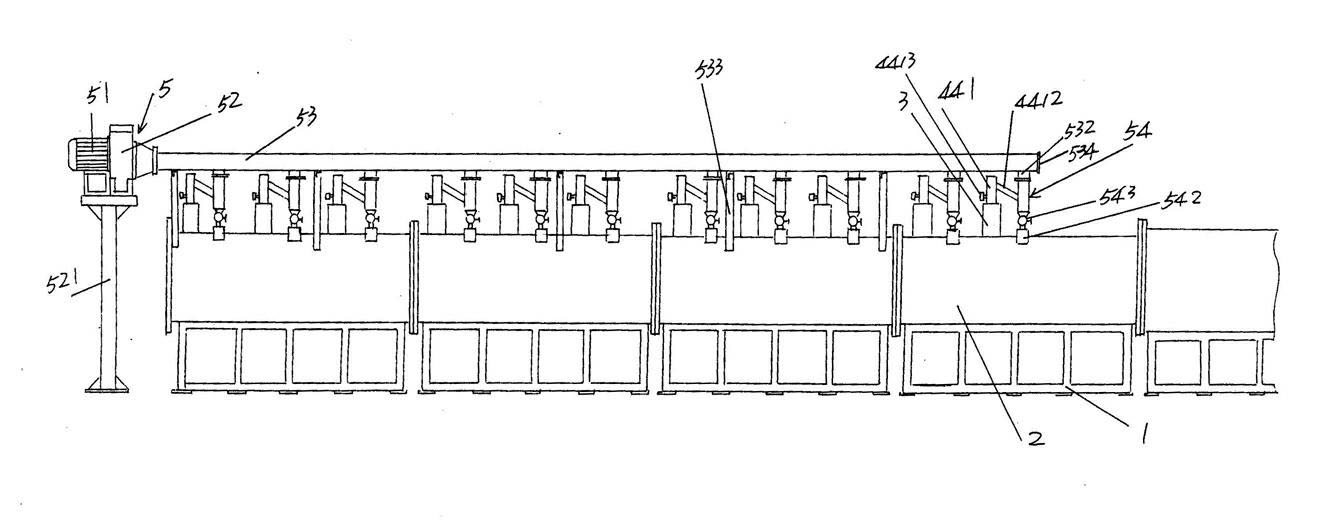
[0022] please see figure 1 and figure 2 , a kiln body support 1 that does not need to be specially defined in the length direction and is preferably a frame structure is provided. On the kiln body support 1 and along the upper part (also called the top) of the kiln body support 1 in the length direction, a kiln Body 2, the kiln body 2 has a furnace 21, used for sintering electronic products such as ce...


PUM


Abstract

The invention provides a tunnel kiln structure for sintering electronic products, belonging to the technical field of kilns for sintering electronic products. The tunnel kiln structure comprises a kiln body support, a kiln body arranged on the kiln body support and provided with a hearth and a group of flue gas exhaust chimneys fixed together with the kiln body in the positions corresponding to agroup of flue gas exhaust holes, wherein the flue gas exhaust holes which are communicated with the hearth and are used for leading out the glue-containing flue gases in the hearth are arranged at the top of the kiln body at intervals along the length direction of the kiln. The tunnel kiln structure is characterized in that heating mechanisms used for preventing the glue in the flue gases from adhering to and being solidified on the inner walls of the flue gas exhaust chimneys are arranged in the flue gas exhaust chimneys; a glue-containing flue gas leading-out and glue collecting mechanism used for leading out the glue-containing flue gases from the flue gas exhaust chimneys in a centralized manner and simultaneously collecting the glue in the glue-containing flue gases is arranged on the outer wall of the kiln body along the length direction of the kiln body; and the glue-containing flue gas leading-out and glue collecting mechanism is connected with the heating mechanisms. The tunnel kiln structure has the following advantages: the sintering efficiency is improved; the requirement for industrialized large scale production is met; the labor intensity of the workers is alleviated; and the energy is saved.

Description

technical field [0001] The invention belongs to the technical field of electronic product sintering kilns, and in particular relates to a tunnel kiln structure for electronic product sintering. Background technique [0002] The electronic products mentioned above are mainly but not limited to the following types: ceramic inductor substrate, ceramic dielectric substrate, lithium iron phosphate powder and powder for various electronic products, etc. The sintering of such electronic products and powder materials for electronic products is usually fired in a box furnace. The colloid will not return to electronic products and / or powder materials, because the inner wall of the chamber furnace will be cleaned once every time it is fired, and the glue scale that has accumulated and solidified on the inner wall will be removed, so as to avoid the risk of failure in the next firing. The glue scale melts and drips and affects the quality of the product. However, there are the followi...

Claims


Application Information

Patent Timeline
Patent Type & Authority Applications(China)
IPC IPC(8): F27B9/00F27B9/30F27B9/36F27D17/00
Inventor 张建方霍李均
Owner 江苏博涛智能热工股份有限公司
Why Eureka
Try Eureka